Introduction
Antenna Theory
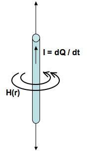
An antenna is a "transition device, or transducer, between a guided wave and a free-space wave, or vice-versa" (Kraus 12). Antennas are composed of conductive material on which a current distribution determines an antenna's defined parameters.
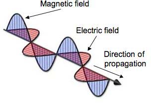
Ampere's Law illustrates that a current-carrying element or antenna creates a time-varying magnetic field which then creates a time-varying electric field and so forth to generate a free-space electromagnetic wave.
When the antenna is attached to a load, it radiates the load's information in an energy-storing electromagnetic wave. The reciprocity of antennas dictates that an antenna can equally translate a free-space electromagnetic wave into guided electrical wave.
Antennas parameters such as gain and impedance are determined by the antenna's shape and size. We will now describe antenna characteristics that antenna designers use to maximize antenna efficiency.
Gain
The gain of an antenna is defined as the ratio of the maximum power density to its average value over a sphere and is often expressed in dBi, where i represents the gain with respect to an isotropic antenna. An isotropic antenna radiates equally in all directions and therefore, has a gain of 1. The common half-wave dipole has a gain of 2.15 dBi. High-gain antennas have gains on the order of 20 dBi.
Resonant Frequency
UHF antennas typically "resonate" or operate at a particular frequency and are sized proportionally to the wavelength of the operating electromagnetic wave.
Radiation Pattern
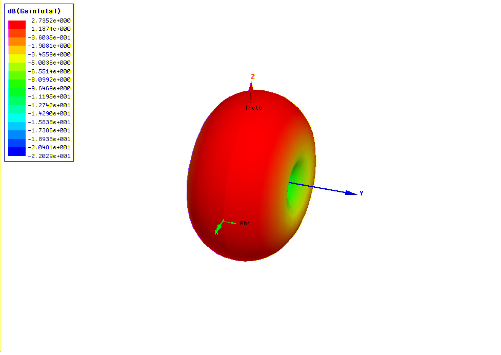
An antenna's radiation pattern is a graphical representation of the strength of the antenna's power density in space. The theoretical isotropic antenna has a spherical radiation pattern but physical do not exist. A half-wave dipole has a doughnut-shaped radiation pattern, radiating in all directions except for the direction of the axis on which it lies.
Polarization
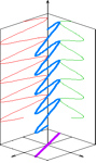
The polarization of an antenna is determined by the electric field of the wave emitted by the antenna. Specifically, the magnitude and phase of the electric field dictate the antenna's polarization. If the magnitudes and phases of the electric field components are equal, the antenna is linearly polarized. If the magnitudes are equal, but the phases differ by 90 degrees, the antenna is circularly polarized.
The electric field components of a linearly-polarized wave project a line onto a plane where the electric field components of a circularly polarized wave project a circle.
 In order for two linearly polarized antennas to communicate with each other, their projected electric fields must be aligned. A circularly polarized antenna however, can communicate with any linear antenna regardless of its orientation. Each polarization type has its advantage; where a circular antenna is orientation insensitive, a linear antenna radiates higher power because all the power is directed in one direction as opposed to being split among the two components. Depending on the application, a reader antenna is either linear or circular, and ideally, the tag antenna should be circularly polarized such that it can be read from any orientation.
Input Impedance
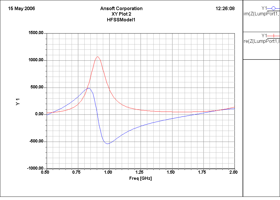
The input impedance of an antenna is defined as the ratio of the voltage to current at the antennaŐs terminals. The length and size of the antenna determine its input impedance. The impedance Z has a real portion, which includes the antenna's radiation resistance R_rad and its ohmic losses, and a reactive portion which contains energy from the fields surrounding the antenna.
Impedance Matching
When electromagnetic energy is transferred from one medium to another, say from an antenna to a microchip, the absorption of energy depends on the relative impedances of the two media. For maximum power transfer between the antenna and its attached load, the impedances of the antenna and the load must be conjugate matches. Their real components should be equal, while their reactive components should be equal and opposite.
More specifically, the reflection coefficient Gamma, is a measure of how much of the transferred energy is reflected back into the original source:
Gamma = (Z_l - Z_a) / (Z_l + Z_a)
When the load impedance of the microchip Z_l is open or shorted, the reflection coefficient Gamma equals 1 and all the energy is reflected back into the antenna. If however, the impedance of the microchip Z_l and the impedance of the antenna Z_a are equal, Gamma equals 0 and all the energy is absorbed by the microchip. With power levels so low in passive RFID, impedance matching between the antenna and the microchip is extremely important to minimize unnecessary losses.
Voltage Standing Wave Ratio (VSWR)
The Voltage Standing Wave Ratio (VSWR) is another parameter used to measure the impedance matching between an antenna and its connected load. It is defined as the ratio of the reflected voltage of the signal over the incident voltage of the signal. The VSWR is expressed in terms of the reflection coefficient Gamma:
VSWR = (1 + Gamma)/ (1-Gamma)
A VSWR of 1 is desirable because no energy is reflected or "lost" from the load back into the antenna.
Bandwidth
In electrical systems, bandwidth is often defined in terms of its half-power, -3dB bandwidth. The half-power bandwidth is the range of frequencies around the resonant frequency at which the system is operating with least half of its peak power.
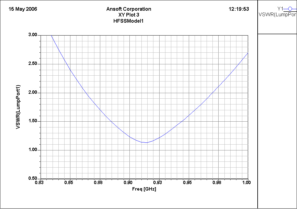
In antenna design, bandwidth is more often described in terms of the VSWR or the impedance bandwidth . The impedance bandwidth is usually specified as the range of frequencies over whcih the VSWR is less than 2 which translates to an 11% power loss.
Microstrip Patch Antennas
A microstrip patch antenna is simply a radiating patch on one side of a dielectric substrate and a ground plane on the other side. The load attaches to a microstrip which connects the antenna's radiating patch to its ground plane. Microstrip patch antennas radiate due to the fringing fields created between the patch and the ground plane and resonate according to the dimensions of the radiating patch.
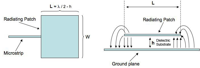
Specifically, the length of the radiating patch determines the resonant frequency as follows:
L = lambda/2 - h
where L is the length of the patch, lambda is the resonant frequency, and h is the thickness of the dielectric. The width W of the patch affects the frequency only slightly, but greatly impacts the impedance of the antenna. The microstrip patch antenna is used in many wireless devices such as cellphones and GPS receivers because of the following characteristics:
- lightweight
- low-profile planar configuration
- can be designed to be linearly or circularly polarized
- capable of multiple frequency operations
- mechanically robust
We focus on microstrip antennas in this paper because of their planar configuration which is essential in RFID labeling applications. Microstrip antennas naturally have low bandwidth and small gain but because of their numerous advantages, many techniques have been developed to increase the bandwidth of microstrip antennas.
Techniques for Making Patch Antennas Broadband
- modified shape patches-- specifically slots
- planar multiresonator configurations
- multilayer configurations
- stacked multiresonator MSAs
- impedance-matching networks
- log-period configurations
- ferrite substrate-based broadband MSAs
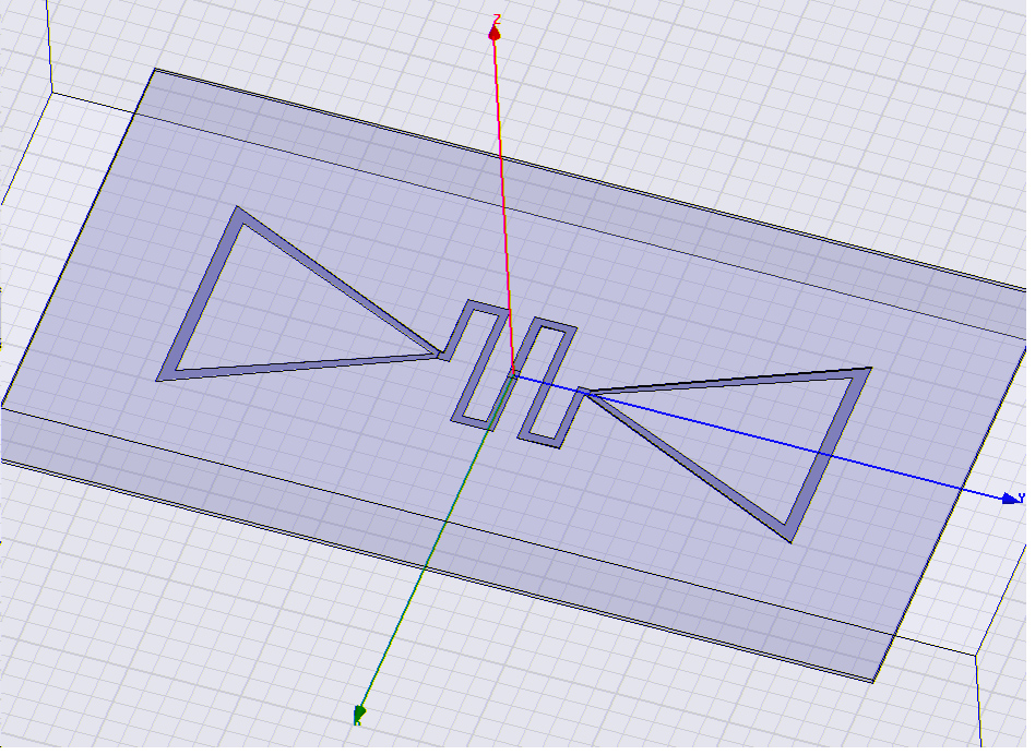
MY BOWTIE ANTENNA (simulated in Ansoft's HFSS)

Genetic Algorithms
A genetic algorithm (GA) is a technique for solving search and optimization problems inspired by evolutionary biology. A GA starts with a pool of "solutions" and through mutations and recombination and "survival of the fittest", the most optimized solution survives. Genetic-algorithm optimizers are robust methods of search that produce global solutions.
Advantages of A Genetic-Algorithm Optimizer
- locates global extrema
- largely independent of initial conditions
- places few constraints on solution domain
- can handle discontinuous and non-differentiable functions
- good for constrained-optimization problems
Broadband Patch Antennas: Good Candidate Problem for GA Optimizer?
The design of a broadband patch antenna is a good candidate problem for genetic-algorithm optimizers because a large number of discrete and continuous and dependent parameters exist that are easily handled with GA-optimizers.
The parameters of a broadband patch antenna include:
- length and width of radiating patch
- position of feed probe
- height of patch above ground plane
- thickness of dielectric material
- dielectric constant of dielectric material
Additionally, the advantages of patch antennas- small weight, size, and cost, bestow additional constraints on the design.
Comparison of Two Techniques
Examples of Patch Antenna Enhancements Using Genetic-Algorithm Optimizers
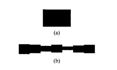


A GA-based optimizer was used to create feedline networks for different shapes of patch antennas. The first image shows a rectangular patch and its corresponding feedline. The second shows a twin-patch antenna and its corresponding feedline. The third image shows a self-complementary rectangular microstrip antenna (SCRMA) and its GA-designed feedline.
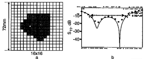

These GA-optimized patch antenna designs demonstrate a fourfold bandwidth improvement from standard square microstrip antennas.
RFID Applications