This project will deal with the possibilities of running boolean logic on cellular automata. I will examine the limits on computational power that arise when the system is scaled up. For instance, how much computing power could be produced if a wallpaper made of cellular automata were configured to process information using boolean logic? This project will also examine the limits in terms of time, cost, and space for such a system.
The first step for this project will be to implement a simple system for running boolean logic on CAs. This will start with a CA system with discrete state in which updates are made based on fixed rules in a rule table. Next, I will have to determine how to implement boolean logic on top of this system using simple fixed rules.
After a basic framework is in place, there are many interesting possibilities for this project to examine. One example would be attempting to run mobile code on the CAs in which the rule tables move from one unit to the next. In this case, the data being processed and information on how that data is processed are both moving through the system, instead of using fixed rules with only the data being propogated.
Finally, this project could also examine the advantages and disadvantages of using synchronous versus asynchronous updates. The costs associated with clocking the system could be estimated.
Examine the differences between using boolean logic for boolean logic vs. boolean logic on CA rule table. What is the cost for boolean logic on CAs vs. regular boolean logic?
Look into fault tolerance at a circuit level and how faults in CAs running boolean logic can be handled.
How does flying boolean logic affect logic on CAs? How can having rearrangable elements affect the cost and effectiveness of boolean logic on CAs?
Construct a CA simulator that uses boolean logic for each CA.
Examine how to make common logic elements out of CAs. Examples are simple logic gates, ring oscillator, LFSR, counter, adder.
I will be comparing the cost of doing boolean logic over CAs as opposed to using standard boolean logic gates. In order to compare the two, I chose an adder circuit that can add an n-bit number and another n-bit number.
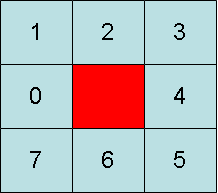
Each element in the simulator is a square surrounded by eight neighbors.
Each CA element has at most two inputs and one output. The two inputs can be chosen from any of the neighbors. Therefore, each input requires 3 bits to encode which of the neighbors to use.
Each of the CA elements can act as any of the possible two-input logic gates. There are sixteen combinations of rule tables for these gates, so these need four bits of information to encode their identity.
With three bits for each of the two inputs and four bits for the type of gate the CA element is acting as, there are 1024 unique configurations for each CA element.
Use CAMachine.java with Circuit 1 or Circuit 2 to see how an adder looks when running through the CA simulator. Circuit 1 adds to single-bit numbers with a single full adder. Circuit 2 adds two eight-bit numbers with full adders in a ripple carry configuration.
To build each CA element out of circuit elements, there are three main sections of the circuit. Each section of the circuit uses a multiplexer to select between the various possible outputs. To select inputs, we use two three-bit multiplexers.
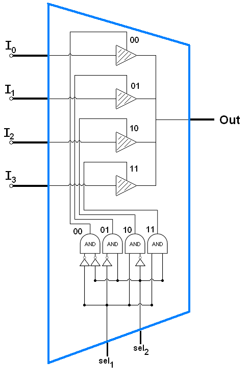
Since this is only a two-bit multiplexer and we need two three-bit multiplexers, our multiplexers will use twice as many not gates, and gates, and tri-state buffers.
Once the inputs have been selected, they will be input to each of the 16 possible logic gates. The outputs from each of these 16 logic gates will need to be selected using a four-bit multiplexer.
So, for each of the CA elements in the larger CA circuit, there must be enough transistors to make two three-bit multiplexers, one four-bit multiplexer, and also each of the sixteen different logic gates.
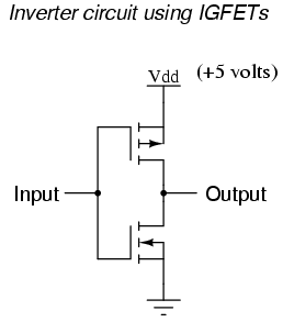
The three-bit multiplexers each require 8 not gates, 8 and gates, and 8 three state buffers. The four-bit multiplexer requires 16 not gates, 16 and gates, and 16 three-state buffers. Then we need one each of the following: not gate, and gate, or gate, nand gate, nor gate, xor gate, xnor gate. Each three-state buffer uses one nand gate, one nor gate, two not gates, and 1 each of n-type and p-type transistors.
So in total for each CA element we need, 97 not gates, 33 and gates, 33 nand gates, 33 nor gates, 1 or gate, 1 xor gate, 1 xnor gate, 32 n-type transistors, and 32 ptype transistors.
We can then add up the number of transistors used in each type of gate to find out how many transistors are used for each CA element.
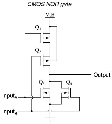
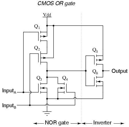
From AllAboutCircuits.com:
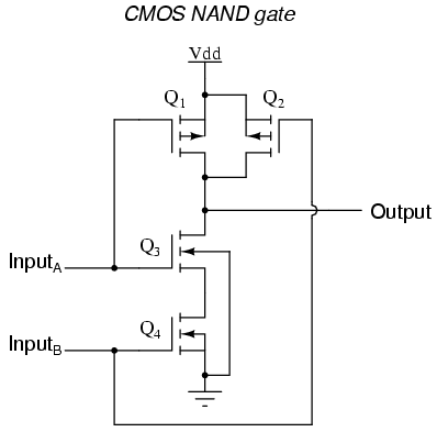
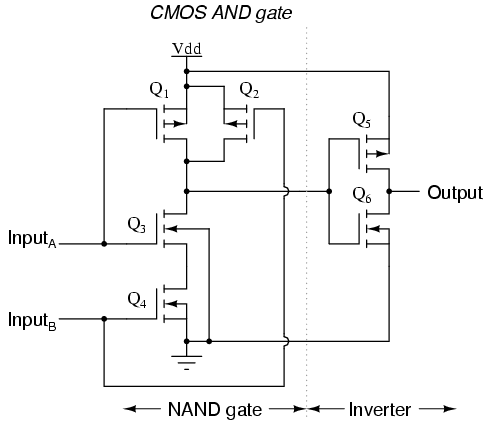
Xor gates take 3 p-type and 2 n-type transistors and xnor gates take 4 p-type and 4 n-type transistors.
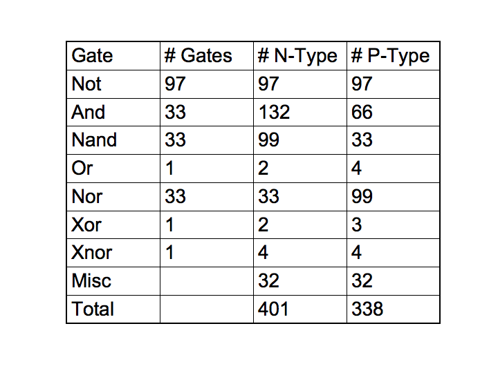
This brings the total to 338 p-type transistors and 401 n-type transistors.
For the single-bit full adder, one needs 2 and gates, 2 xor gates, and wire when making it with boolean logic. This translates to 10 p-type and 10 n-type transistors.
For the single-bit full adder on a CA, one needs the same 2 and gates and 2 xor gates, and wire. However, wires are also using the same number of transistors since they are just like every other CA element in the CA circuit. The single bit full adder needs 17 wire elements. This means there are 21 total CA elements for a single bit full adder, which requires 7098 p-type and 8421 n-type transistors. In other words it requires hundreds of times more transistors for the CA model than with the standard boolean logic gates.