|
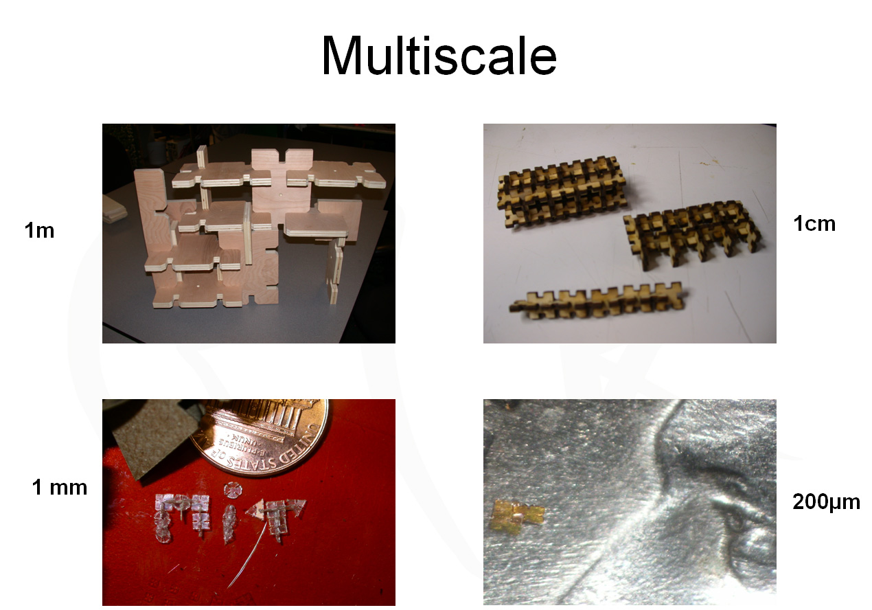
Present
the results
Finite element simulations 1.0
With Femlab I obtained the following results :
I am not happy with the results
because :
- I can't really measure on
the Instron the stress strain fields I am obtaining
here. I would like to find a way in Femlab to
calculate the necessary force to put 2 parts
in contact.
- The only material properties
I have are for some RED HARD WOOD (not cardboard)
- The parts don't seem to move
during the simulation even if I am doing a dynamic
simulation (not static !)
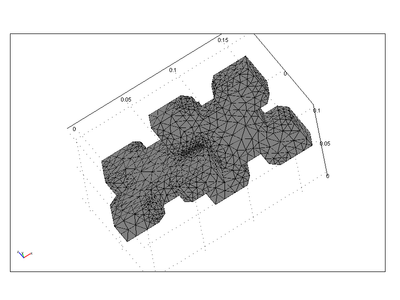
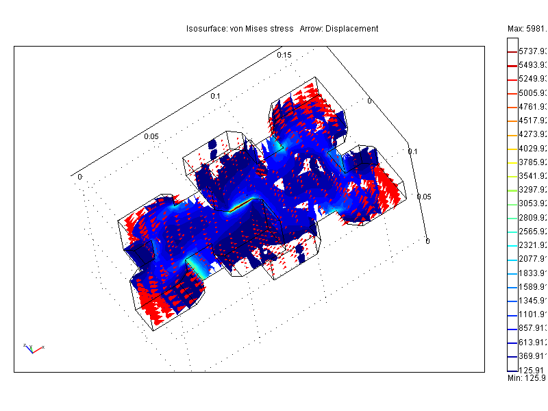
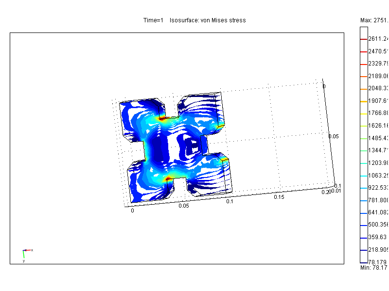
But here are the results. The
first picture is the drawing with the mesh. The
dimensions are meters. The 2nd picture is the
von Misses strain field isosurfaces and the arrows
the displacement..
I applied 1000 N on each GIK parts standing in
free air.
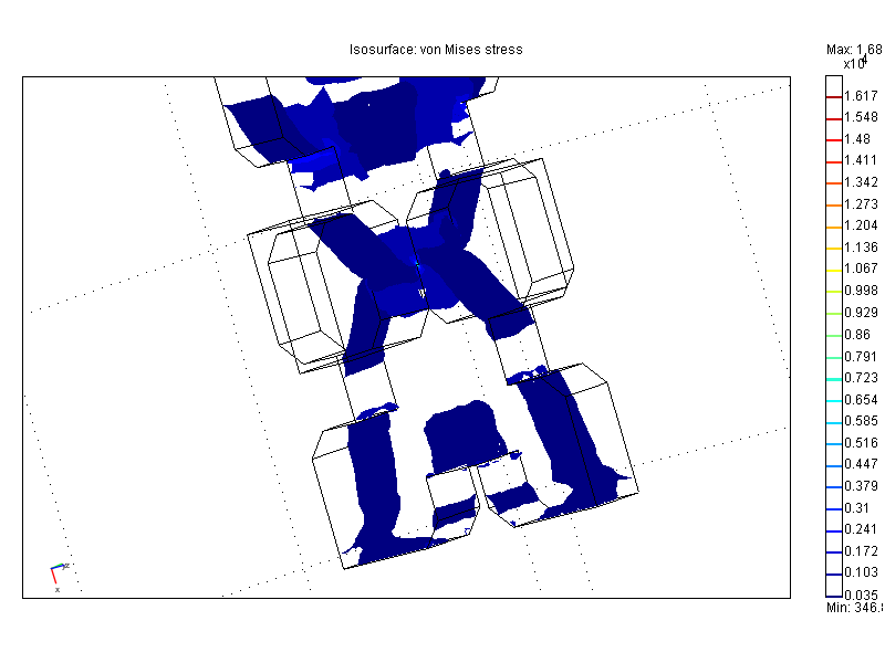
Here is the stress field of a
single GIK part when pressed against a flat surface
:
May 22nd : Now that I know how to use Femlab I
simulated precisely my experiment (2 GIKs in contact,
a little bit too large for each other ) and here
are the results :
Also here are the first results with the Instron
(it's working ! ) (Comment on May 15th : results
obtained by hand , by writing down the values
indicated on the screen and moving the Extensiometer
by discrete macro steps ):
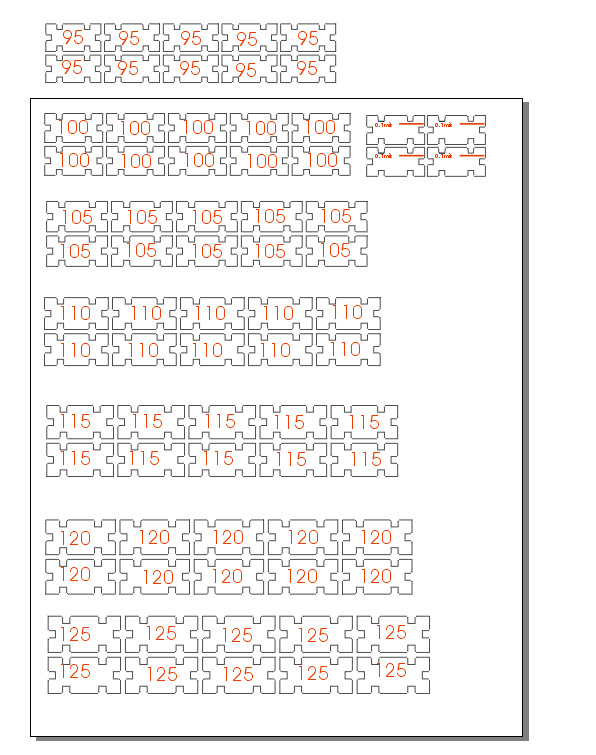
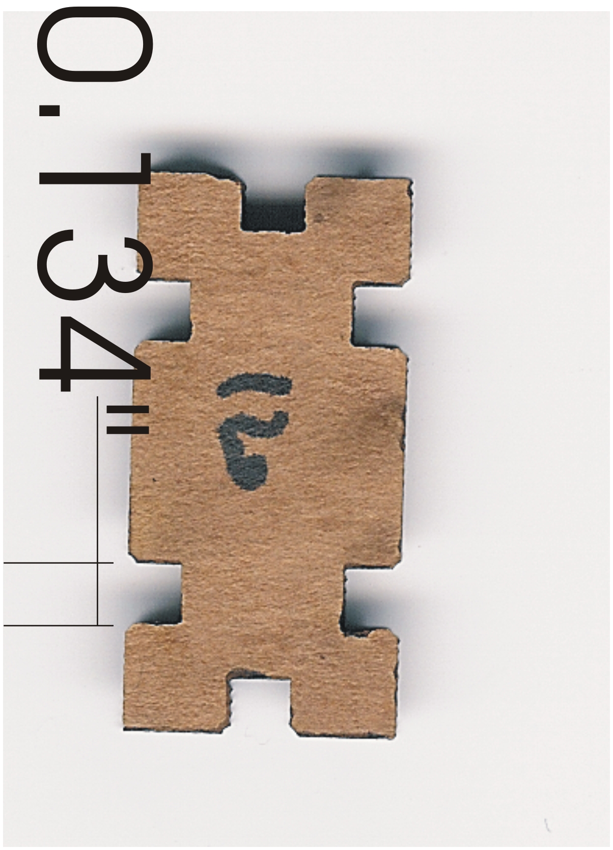
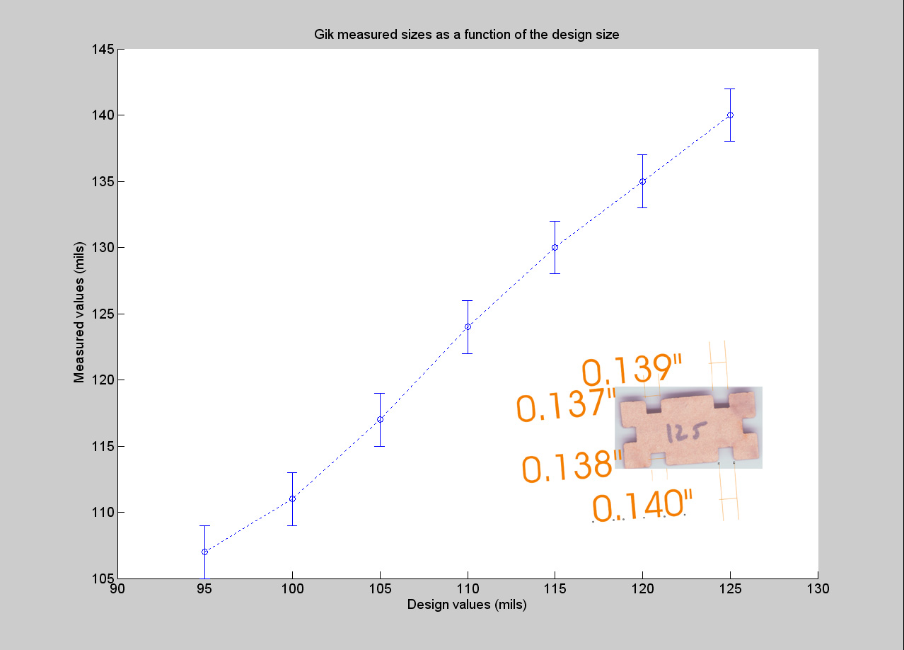
In order to get meaningfull measurements with
the Instron we need to be able to measure well
a GIK part dimensions. I've been trying to use
the scanner which should go to 1600DPI but I couldn't
find out how to use it at higher resolution that
300DPI. 300DPI is not enough, but here is what
we get with it : This is a cardboard GIK part
made out of 110 mils thick ECT44 cardboard. The
slot's width should have been 120 mils ( as indicated
by the writing on the part). The measurement was
done with Corel based on the resolution of DPI
and counting the number of pixels.
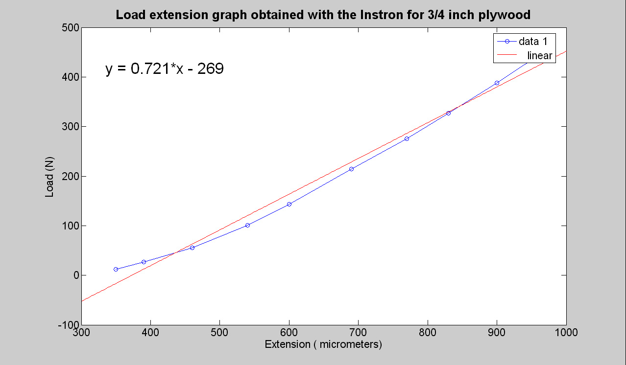
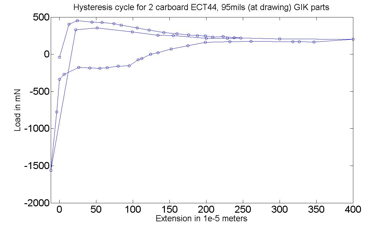
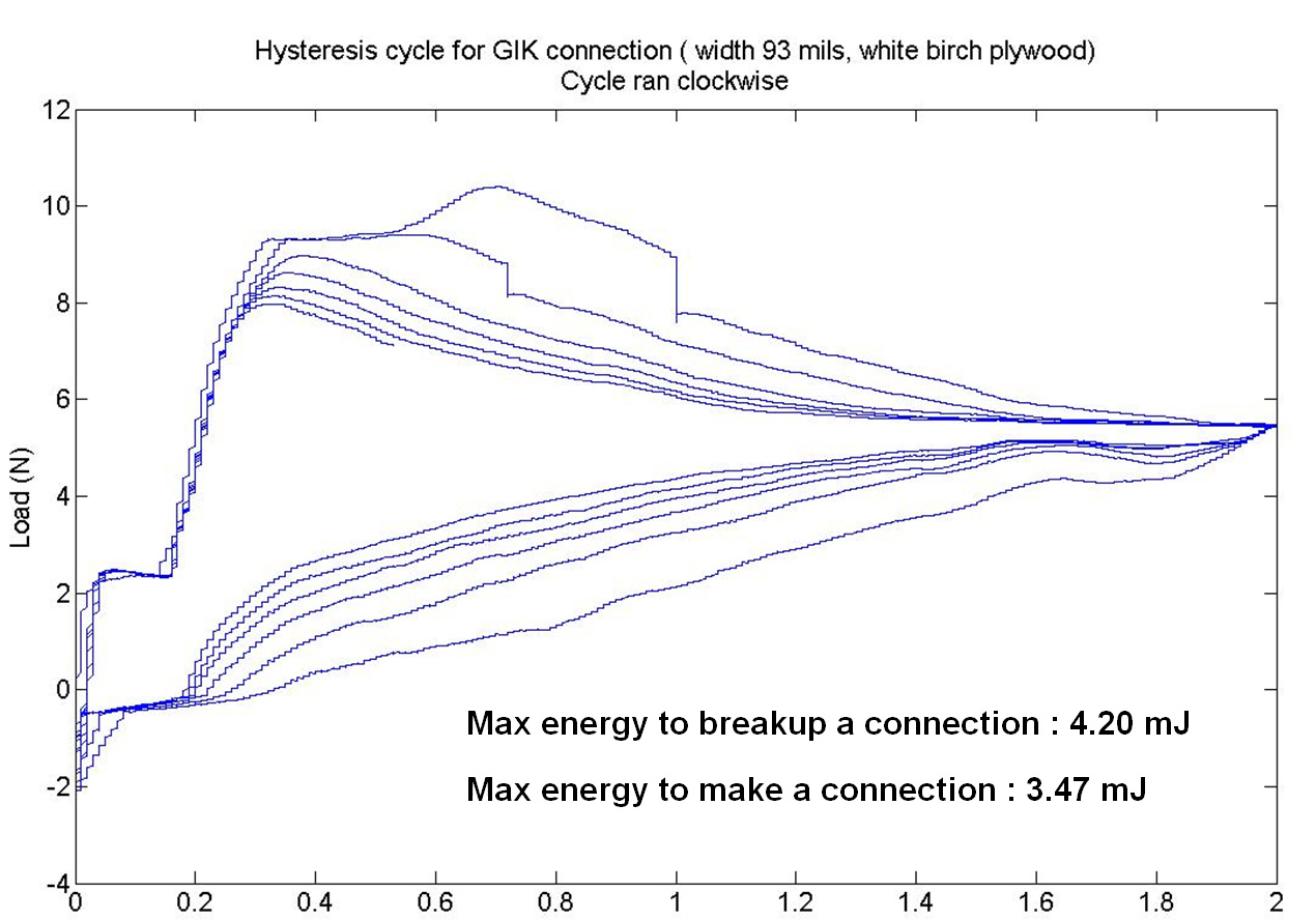
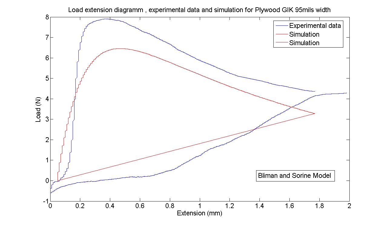
And the STATIC ( = at equilibrium) Load vs Extension
hysteresis graph for 2 95 mils (at drawing) GIK
parts made out of cardboard ECT44 110mils thick
(or about) :
We can see the hysteresis cycle. However this
diagram was made by hand and computer control
is necessary. The next step will be to use the
computer to control the Instron.
Measuring GIK slot sizes :
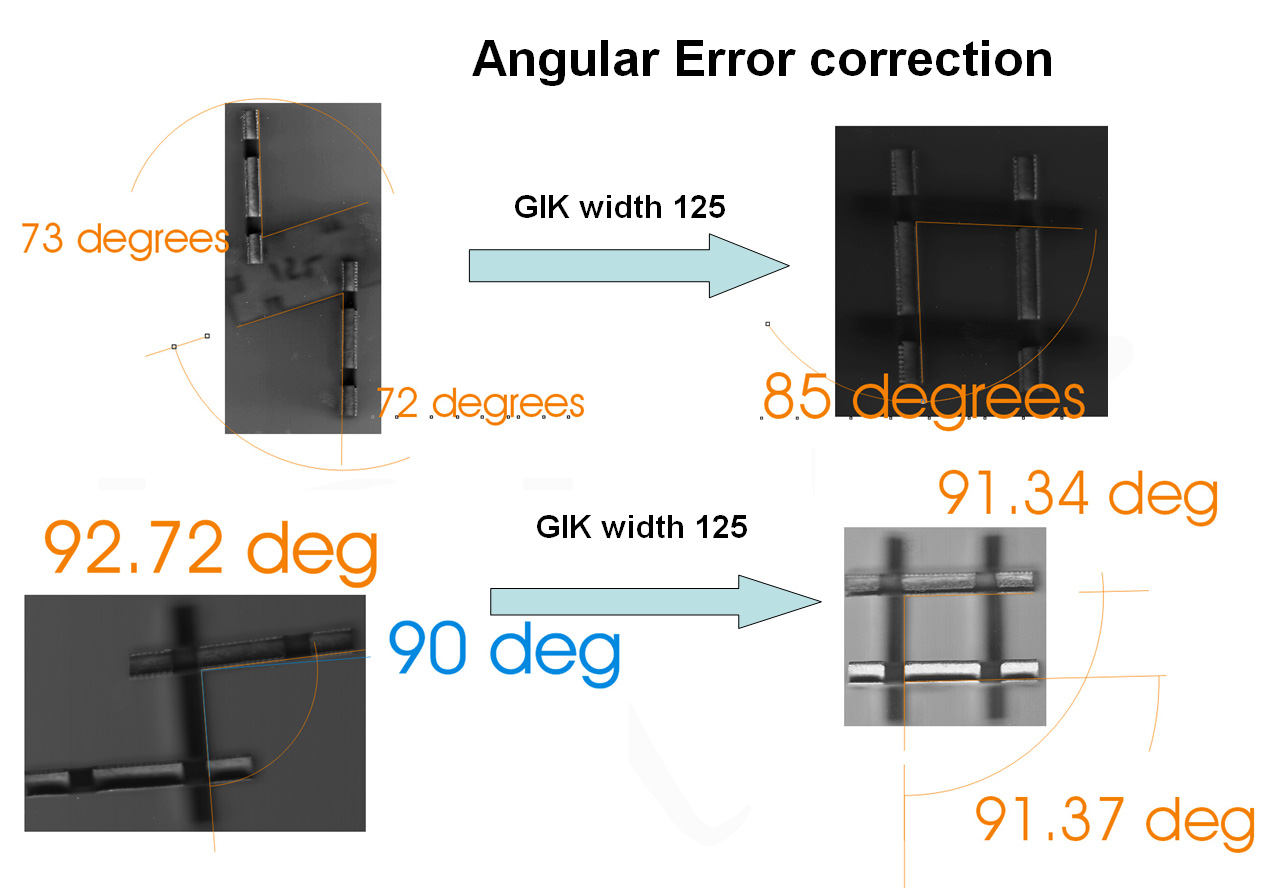
Measuring the error angles of 2D vs 3D structures
for GIK 125 and GIK 105 :
Conclusion : building 3D is reducing the GIK
freedom of move (also called structure looseness)
!
May 15th :
It took me 2 weeks to be able to talk to the
Instron. I gave up using Ethernet to that purpose
( I just can't find a way to make it work and
my project was about GIKs not
learning how to program low level Ethernet). Once
I got the GPIB talking ( using an old PCI-GPIB
card next to the Instron) , taking all these results
took 2 days.
So here are the results ( the pictures a well
organised because I am also giving a talk today
at noon and I made nice slides :) )
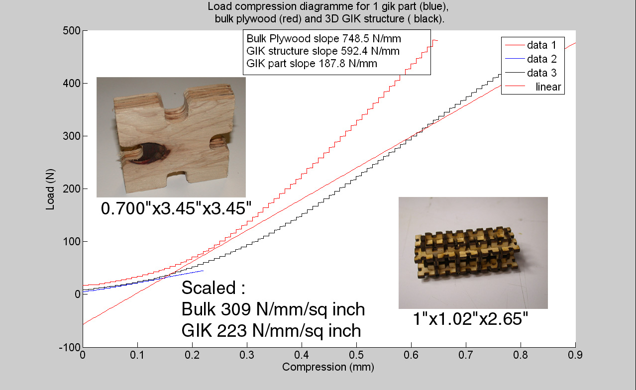
First the material behavior :
Comparing bulk plywood with GIK structure :
 Load
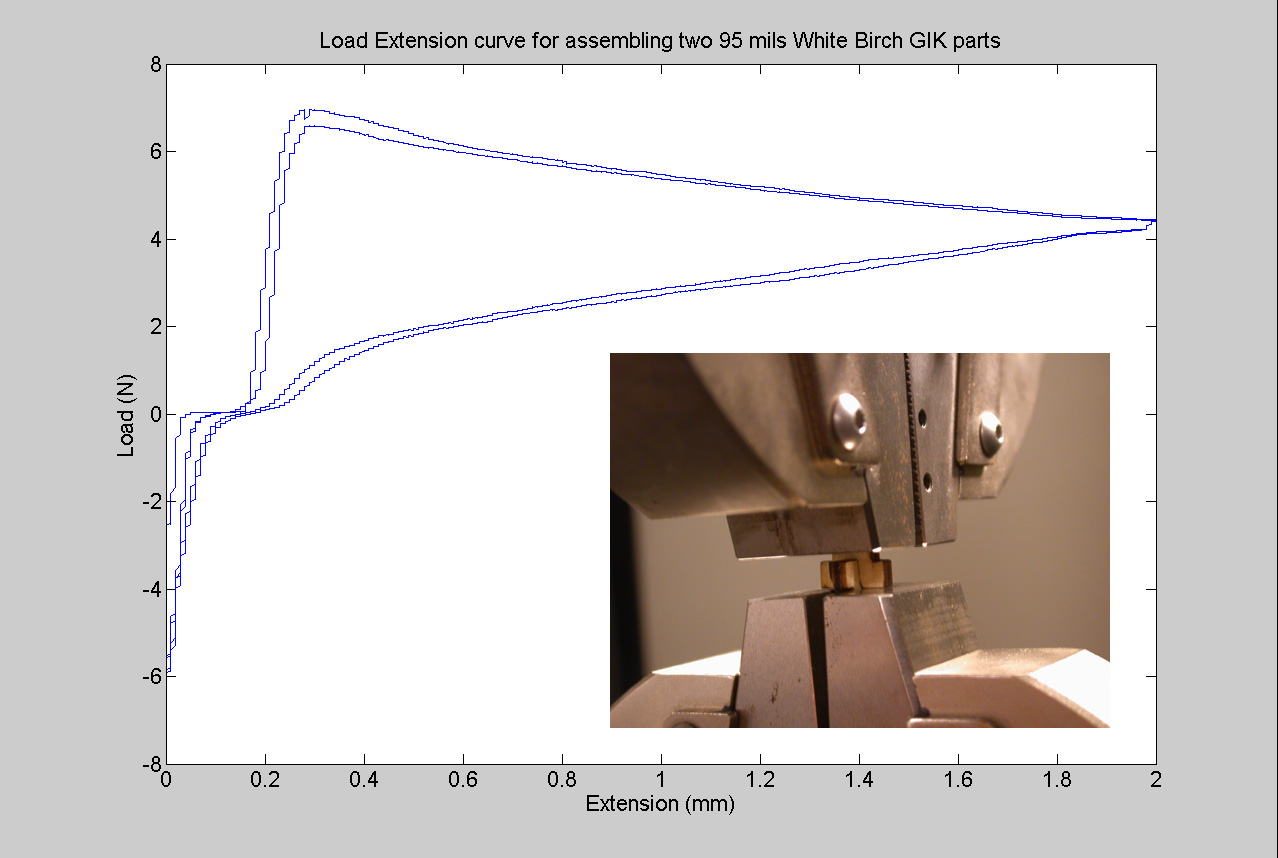
extension curve for 2 GIK parts : Load
extension curve for 2 GIK parts :
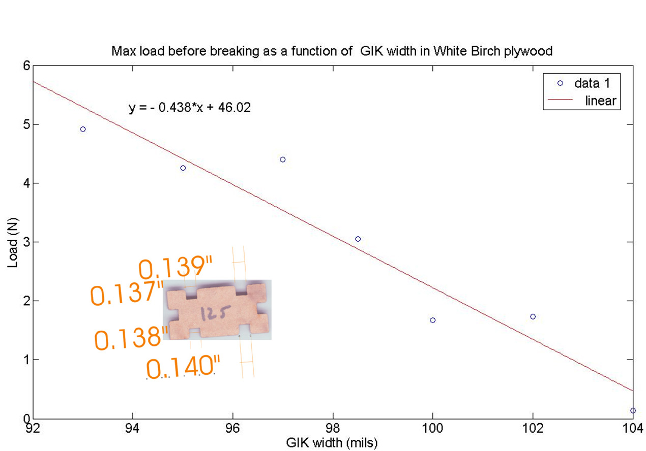
 Max
load before breaking as a function of GIK width
: Max
load before breaking as a function of GIK width
:
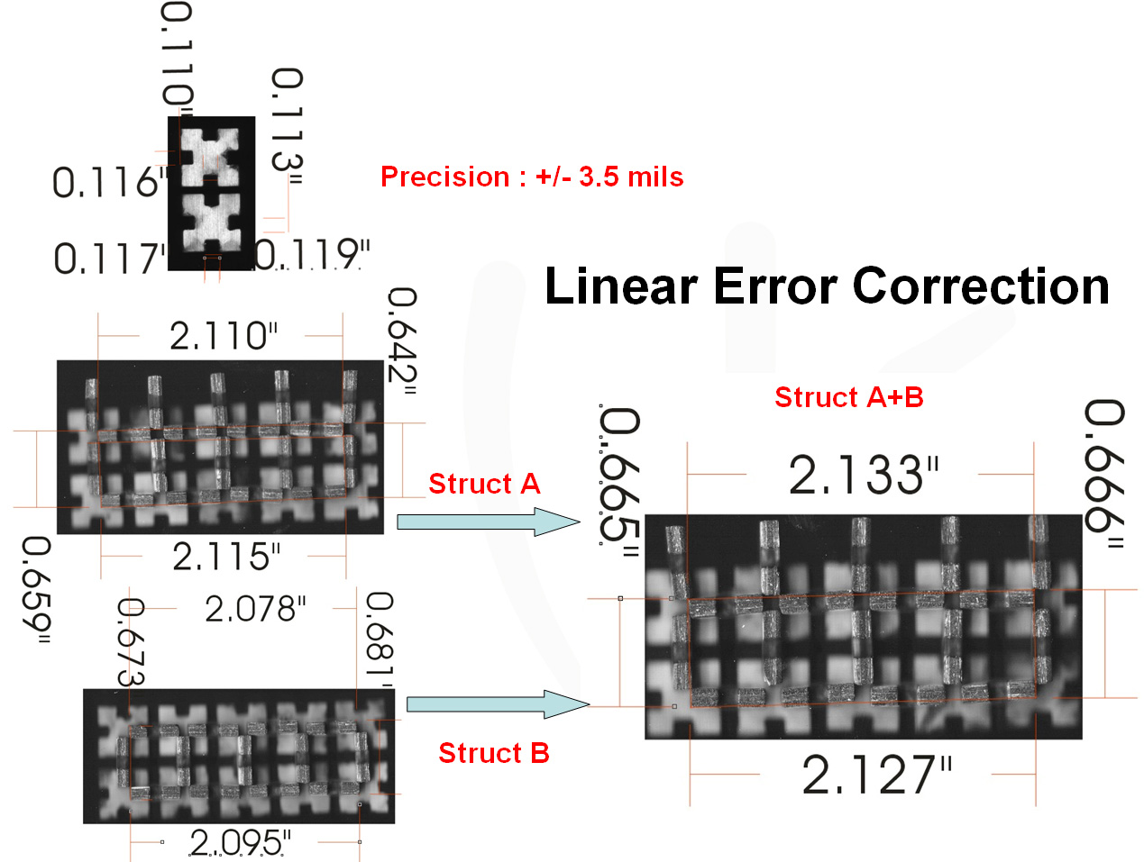
And now error correction.
There is angular error correction ( showed with
cardboard Lego GIKs)
And linear error correction : showed with plywood
white birch GIKs :
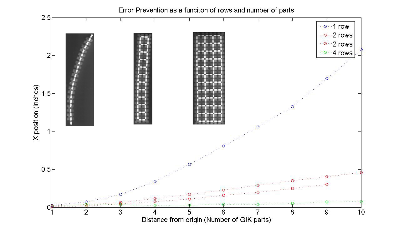
Now if we do the same think with Delrin and plot
error VS size of the structure this is what we
get :
May 15th : Last thing to be done is to make a
model of the friction and paste it to the measurements,
if necessary with parameter identification. DONE
The model is by Bilam and Sorine ( see this link
: www.control.lth.se/~kja/friction.pdf)
. I implemented the model in Matlab and fitted
the model to the experimental data. This is the
Matlab code :
"function F = frictionmodel(param,x)
%Bliman and Sorine
%change the sign of V for the way you go around
the cycle
v=1*1e-3/60; %1mm/min to m/s
d=2e-3; %in m
T=d/v; % in s
numberofsteps=1000;
dx=d/numberofsteps;
dt=dx/v;
%not used in the fitting model
%x=[0:dx:2e-3]; % position in m
ds=dx;
F=zeros(length(x),1);
xs=zeros(2,length(x));
%constantes experimentales :
%fs=0.7 %N
%fk=0.45 %N
%se=0.02e-3 %m
%sp=0.03e-3 %m
fs=param(1); %N
fk=param(2); %N
se=param(3); %m
sp=param(4); %m
%intermediates
m1=(fs-fk)/fk;
m2=exp(3*se/sp);
%p= solution de :
% (m1*m2+2)/(m1*m2)*log(p)-(p-1)*log(m2)==0
pvector=[1.1:1e-4:10];
[a,b]=min(abs((m1*m2+2)/(m1*m2)*log(pvector)-(pvector-1)*log(m2)));
%we found p!
p=pvector(b);
eta=(m1*m2+2)/(m1*m2*p+2)*fk;
epsilonf=sp/3;
f1=(m1*m2+2)*p/(2*(p-1))*fk;
f2=(m1*m2*p+2)/(2*(p-1))*fk;
A=[-1/eta/epsilonf 0 ; 0 -1/epsilonf];
B=[f1/eta/epsilonf ; -f2/epsilonf];
C=[1 1];
for n=1:(length(F)-1)
s=x(n);
dxs=ds*(A*xs(:,n)+B*sign(v));
F(n+1)=C*xs(:,n);
xs(:,n+1)=xs(:,n)+dxs.*dt;
end
"
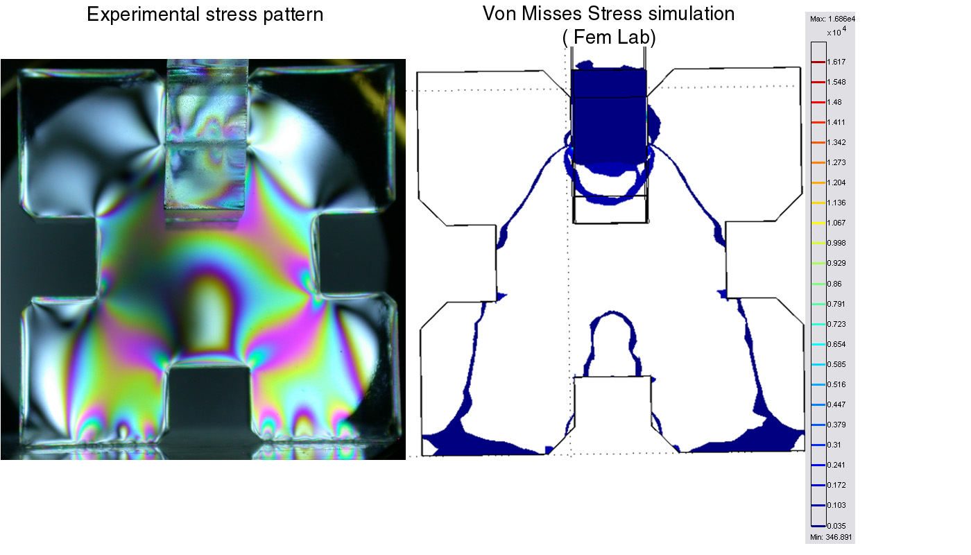
May 22nd : Using 2 polarizing lenses from here
( http://scientificsonline.com/product.asp_Q_pn_E_3038605
) and by making a set-up ( with a lot of scotch
tape, a hacked and prepared microscope lamp and
a soldering vice :) ) under the Instron I recorded
stress patterns ( using my camera Nikon 995 with
a tripod ! ) . The sampels where 1/2 inch thick
Acrylic GIK parts
Compare
results to existing literature
May 15th :
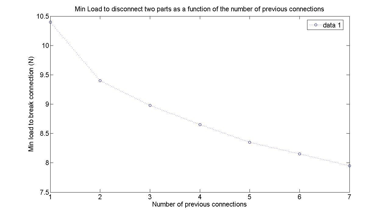
The Hysteresis cycles correspond
exactly to what is found in literature ( see :
www.control.lth.se/~kja/friction.pdf)
May 22nd Fianl Results :
1. I made a finite element simulation
of stress/strain in a GIK part, and in 2 GIK parts
assembled.Here are the results :
2. I recorded an hysteresis cycle
with the instron and simulated it's behavavior
(see up here for the model), here are the results
:
3. The material behaves like a bulk materials
:
4. Error prevention :
|