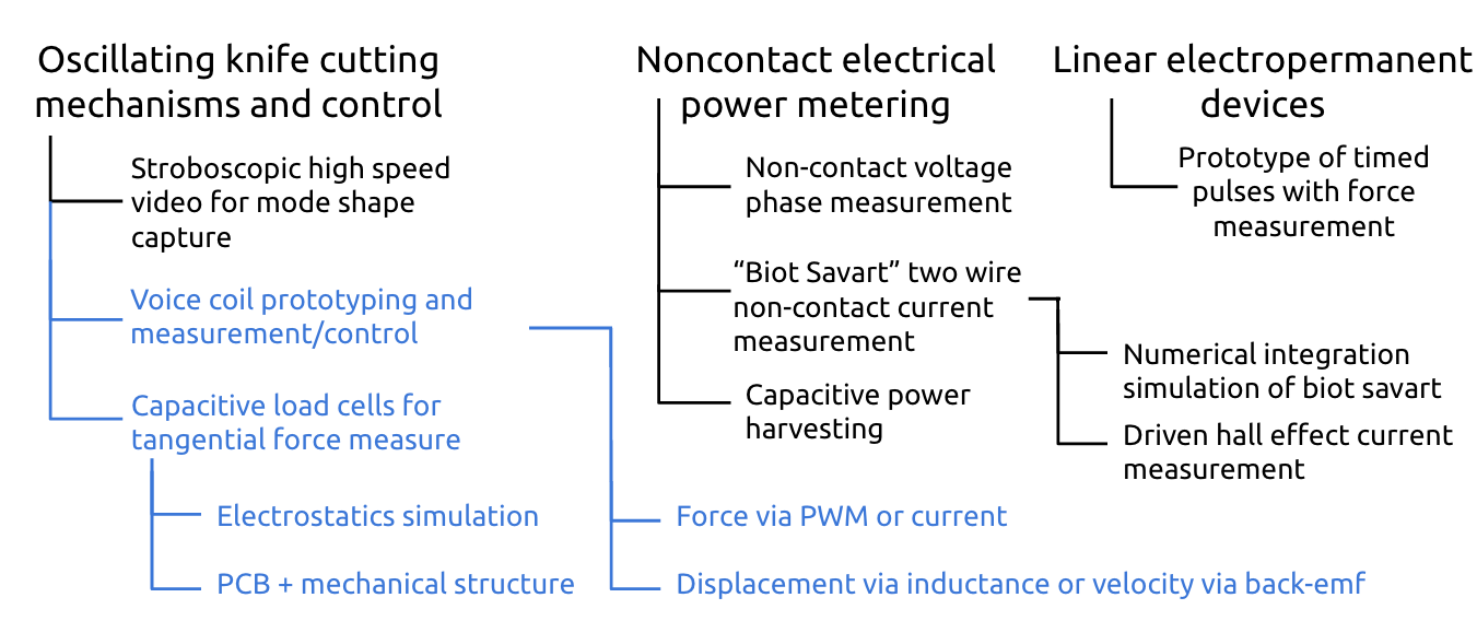
Welcome to my PIT project page. It's a mess! The map above shows roughly the content of this page, and blue is what I'm calling my "project".
Roughly, I'd like to have a better understanding of what is happening when the vinyl cutter cuts, and what is happening when an ultrasonic knife slides through hard plastic. Originally, I wanted to look at the higher frequency phenomenon, but it proved easier to start lower. To this end I made a voice coil driven knife and set about instrumenting it to measure displacement of the knife and the forces on it.
First, can we measure displacement of the voice coil and force applied by a voice coil accurately enough to characterize a cutting process? There are a variety of techniques available to estimate the position of a voice coil actuator in operation. The most common is to actually measure the velocity of the actuation, which produces a strong back-emf signal from the coil seeing a time varying magnetic field as it enters or exits the shell. A good overview is in Self-sensing applications for electromagnetic actuators. There is plenty of signal to measure in this case, but this method suffers from integration drift (we must integrate velocity to find position). We can use other indicators to "reset" the position estimate, but this becomes messy.
In "Sensorless position control of voice-coil motors for needle-free jet injection", the authors superimpose a high frequency signal onto the driving voltage of the voice coil, and filter it out of the current signal to measure the inductance of the voice coil. In many VCA designs, the inductance varies linearly with position, as the coil enters and exits the region of high permeability in the flux guide shell. This approach seemed very interesting, but filtering the measurement signal from the driving signal was the cause of some innacuracy. I thought I might be able to make an inductance measurement just using the driving signal itself (a pwm pulse train). Come to find out, after doing the measurements shown below, someone had already done it! I'd like to clean up my work and compare with them now.
Some of these approaches also give the force applied by the voice coil actuator, but we also need to measure the tangential cutting forces to fully instrument our cutting process. For this, resistive load cells are commonly used. I've always wanted to make my own, but after reading I became scared of the nightmare of surface prep and adhesion of the thin film resistors to make an accurate measurement. I've made capacitive force sensors before, but that didn't have the repeatability required of a load cell. Capacitive load cells are used in industry, mostly in situations where durability is needed. I found a strangely worded but useful article: A Novel Force Transducer and Load Cell Design Using "Leaky" Electromagnetic Waves. The author presents a moving dialectric capacitive load cell where the control electronics and structure are completely independent. In my understanding, this has a number of benefits:
Now, I did have some problems with the moving dialectric designs in the article. First, the author talks about the freedom to choose materials, but the same material is providing the dialectric constant as well as the elastic modulus. This is an unnecessary correlation. I wanted to decouple these in my design. Second, I wrote simulations that show the moving dialectric response isn't nearly as sensitive as a parallel plate response (which makes intuitive sense). In my design, I keep all the electronics in a monolithic piece, but I move a conductor rather than a dialectric. The response of this isn't as large as parallel plate, but it is significantly larger than moving dialectric.
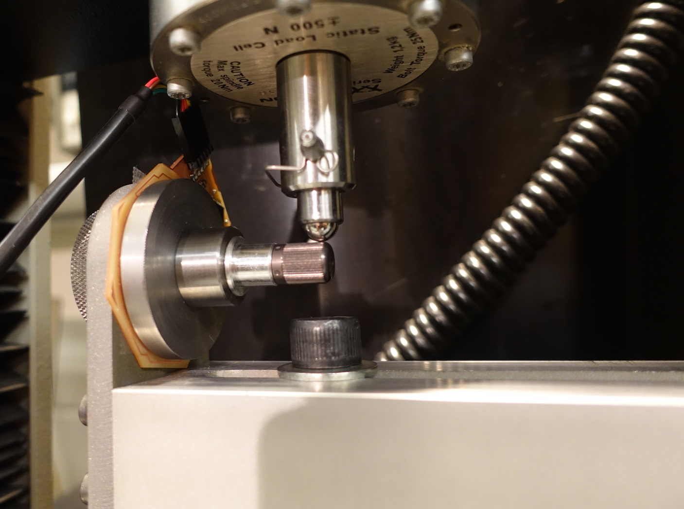
Conveniently, to address all of these issues, I standardized my design around O-rings, taking the design case to be the common task of mounting a tool heat (knife, spindle, etc.) to a plate (e.g. a linear carriage). Often this is done by inserting a bolt or rod into a hole, and clamping down on the plate. By placing O-rings inside this clamp, we can create a small amount of compliance with a large degree of control (due to the wide availability of O-rings of differing dimensions and materials like silicone, rubber, PTFE, etc.). In prototyping this load cell design, I wanted to answer whether this design choice could accomodate the requirements of my knife measurement problem: Could I make the interface stiff enough? Could I measure a meaningful signal?
What follows is a working log from the semester, addressing the questions posed above.
I've been experimenting with cutting and folding of sheets to make large structures, and I've been curious about cutting techniques beyond the two most common (drag knife and laser cutting). Large displacement oscillating knives are used for thick, low density materials, but small displacement oscillation produces really impressive results, especially fibrous materials. In paricular, one key use of ultrasonic cutting is in the cake industry, where the medium to be cut need not be disturbed. I would want to focus on low-power, low-displacement sonic and ultrasonic cutting, comparing actuator types, frequency, displacement, power requirement, cutting speed, and types/thicknesses of materials cut. In particular, I'm curious about cutting fibrous materials (Tyvek, papers and vulcanized fibers, etc.)
Here is a crazy video of someone cutting through a stack of CDs by hand with an ultrasonic knife. Here's a video of cutting through carbon fiber pre-preg.
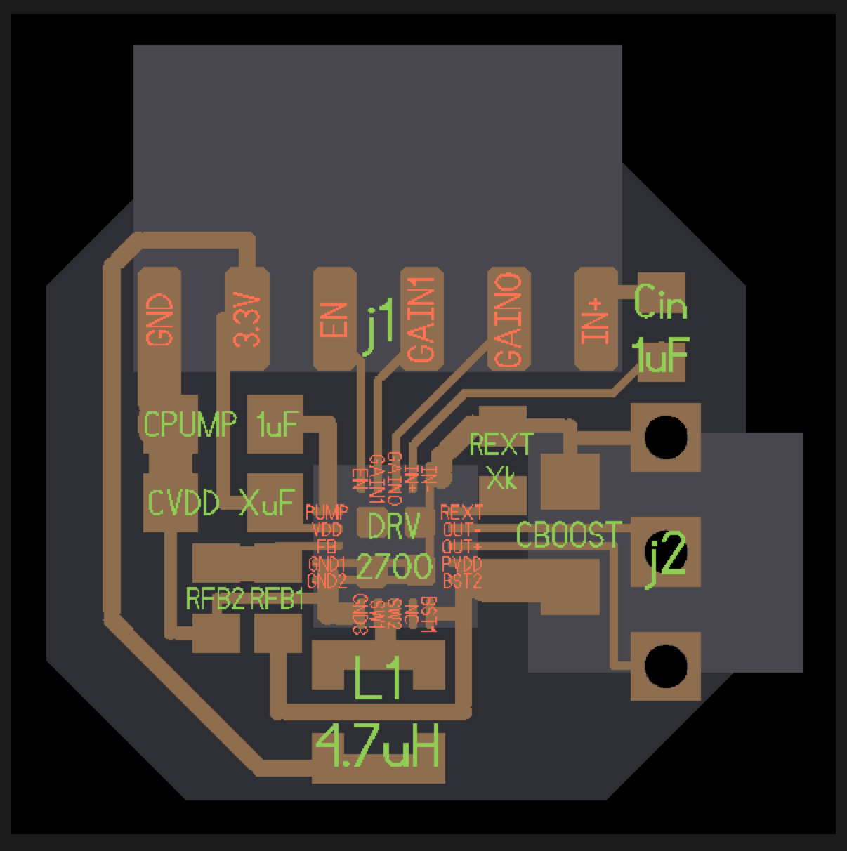
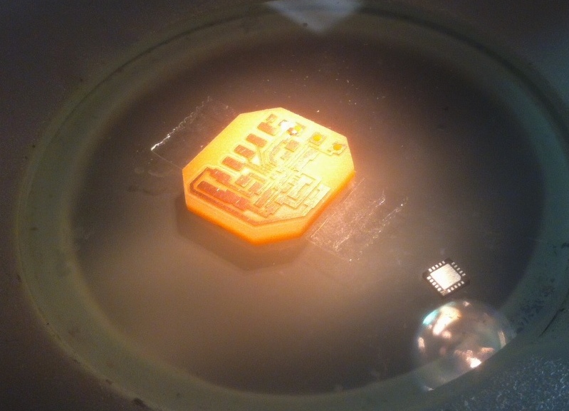
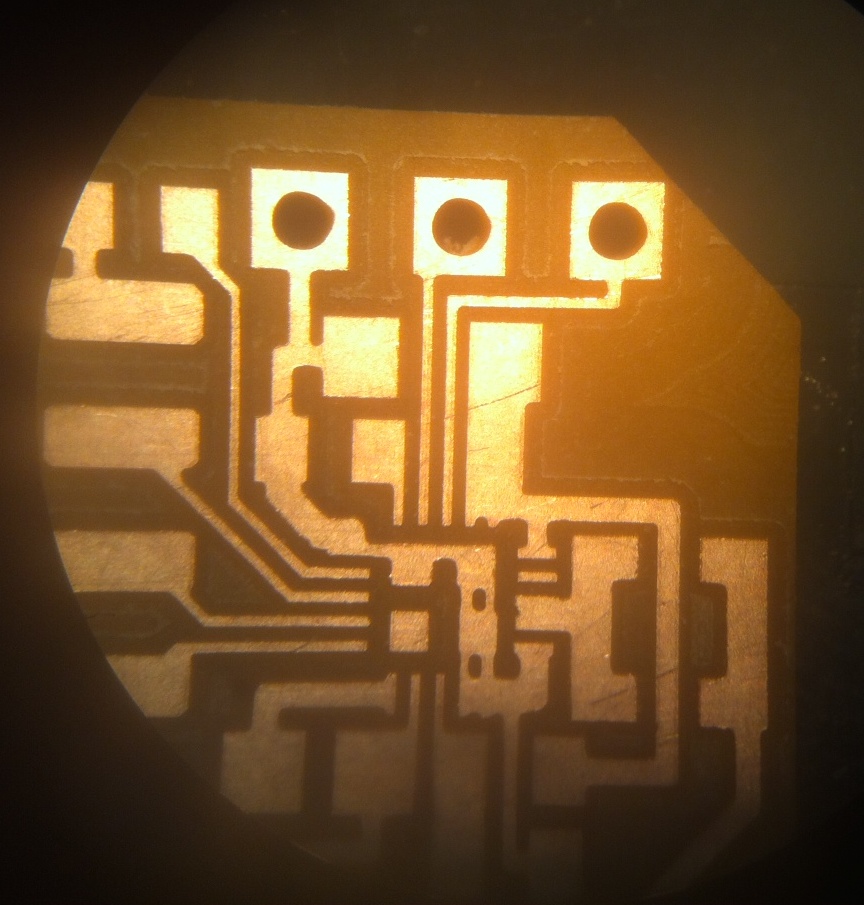
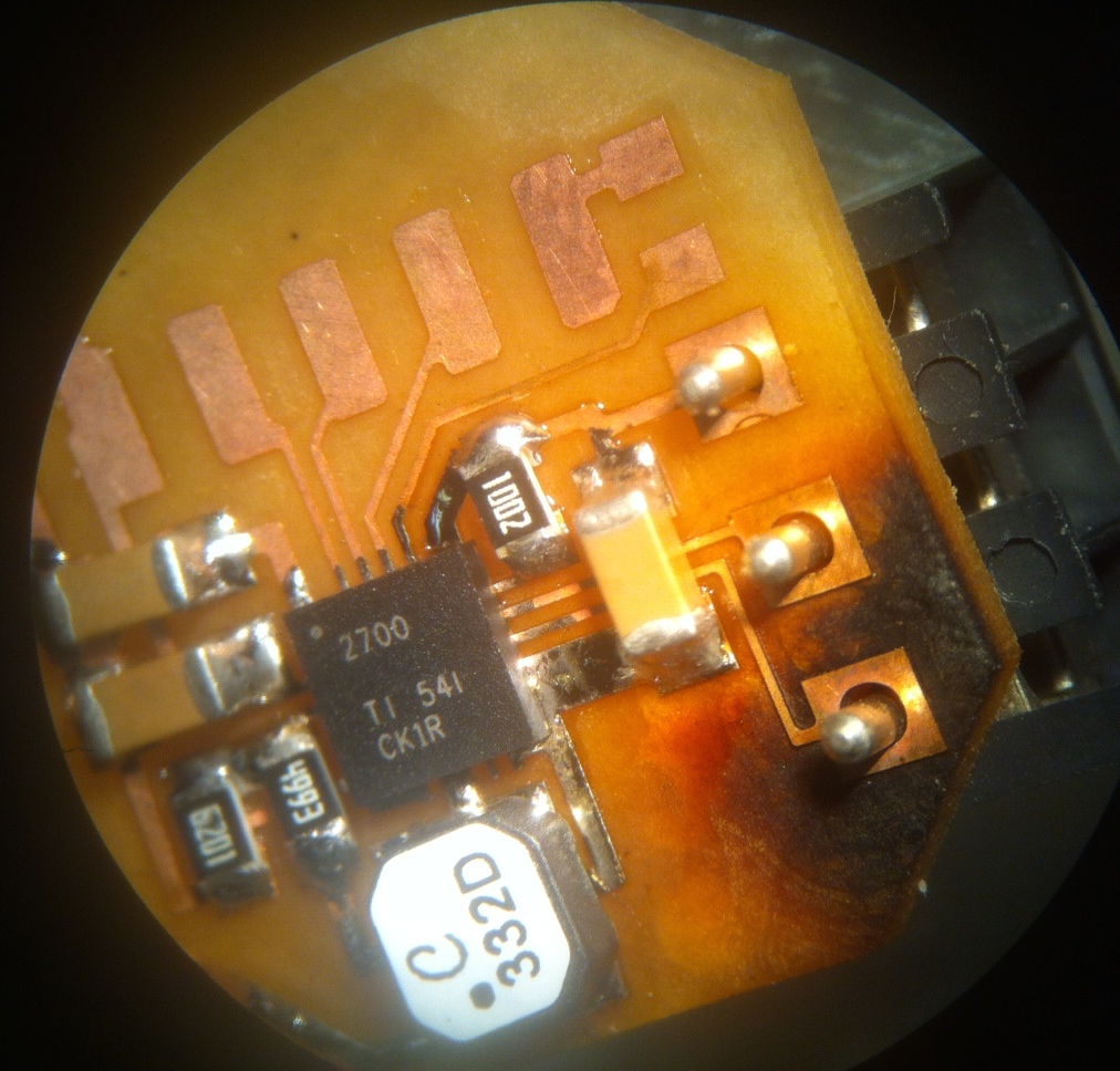
Over winter break, I experimented with building a piezo driver using TI's DRV2700 chip (a picture is shown below). I didn't get this device working properly yet, but I'd love to return to it. In particular, the best hobbyist piezo drivers I've found online are these boards. They cost $80 and use the lower power DRV8662 from TI. In contrast, the DRV2700 costs $8 from digikey and can drive a 100nF capacitive load, 200V peak-to-peak nearly at roughly four times the frequency (300Hz vs. 1200Hz) in boost mode. The DRV2700 also can also be used in a 1kV flyback mode, to drive high voltage piezo actuators.
Besides just providing a cheaper option, I'd like to explore techniques for finding resonances of piezo driven systems (a.k.a., knives). When I was experimenting with ultrasonic welding, I had no end of trouble matching horns to the transducer frequency without just reflecting the energy and tripping the driver's protection. If I build my own driver, I can provide an interface where the user can tune the drive to match the mass and geometry of the device being driven. If this proves too difficult with TI's part, I could start from designs like this one to build a (bulkier) amplifier with more control.
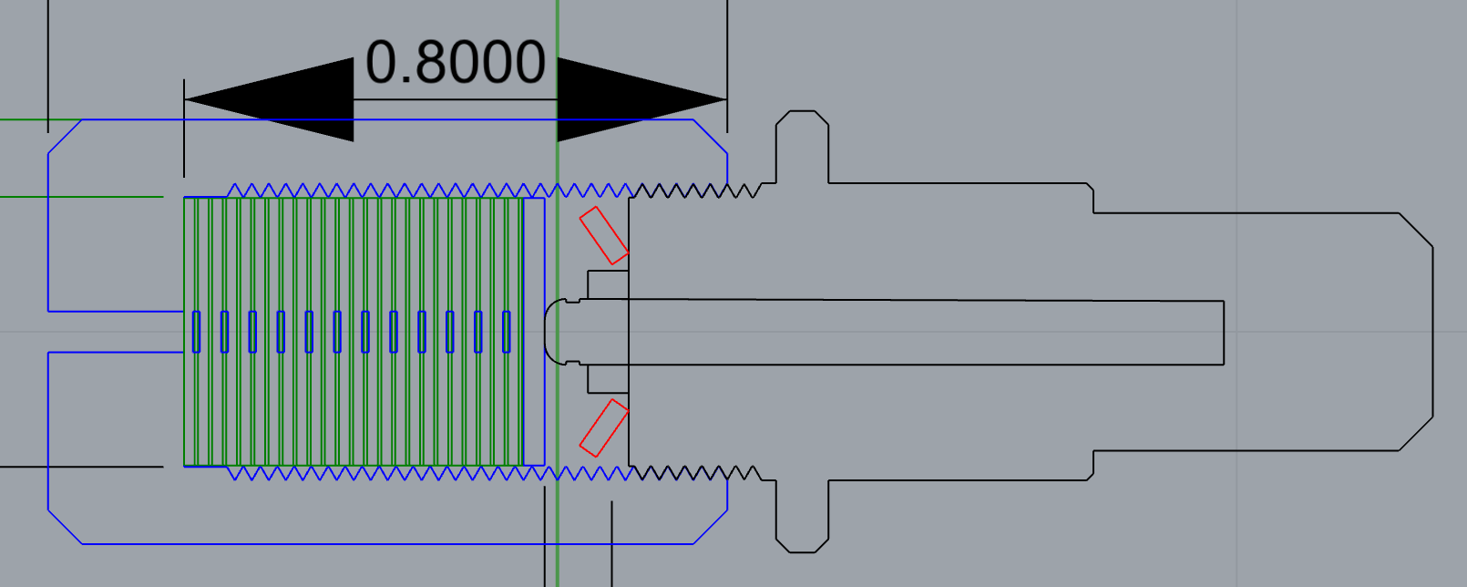
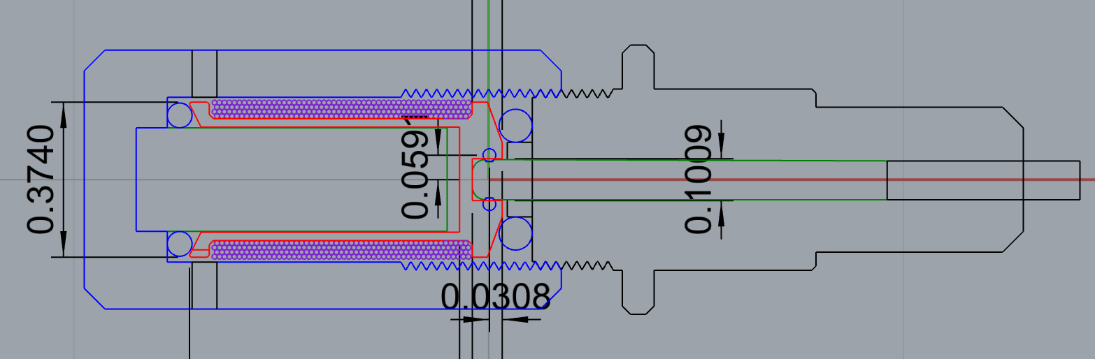
Since piezo stack actuators are so expensive, I'd like to experiment building my own from individual piezo disks. The disks are relatively inexpensive (here's a pack of 10x .4mm thick x 10mm diameter for $17). The trick is to properly assemble and load the piezo elements so their individual small displacements add into a larger total displacement. Below are two design sketches for units that fit into a standard Roland drag knife module -- one uses interdigitated, vinyl cut electrodes to actuate a stack of these piezo disks. The other is a competing design, using a moving voice coil (a lower force, but higher displacement actuator).
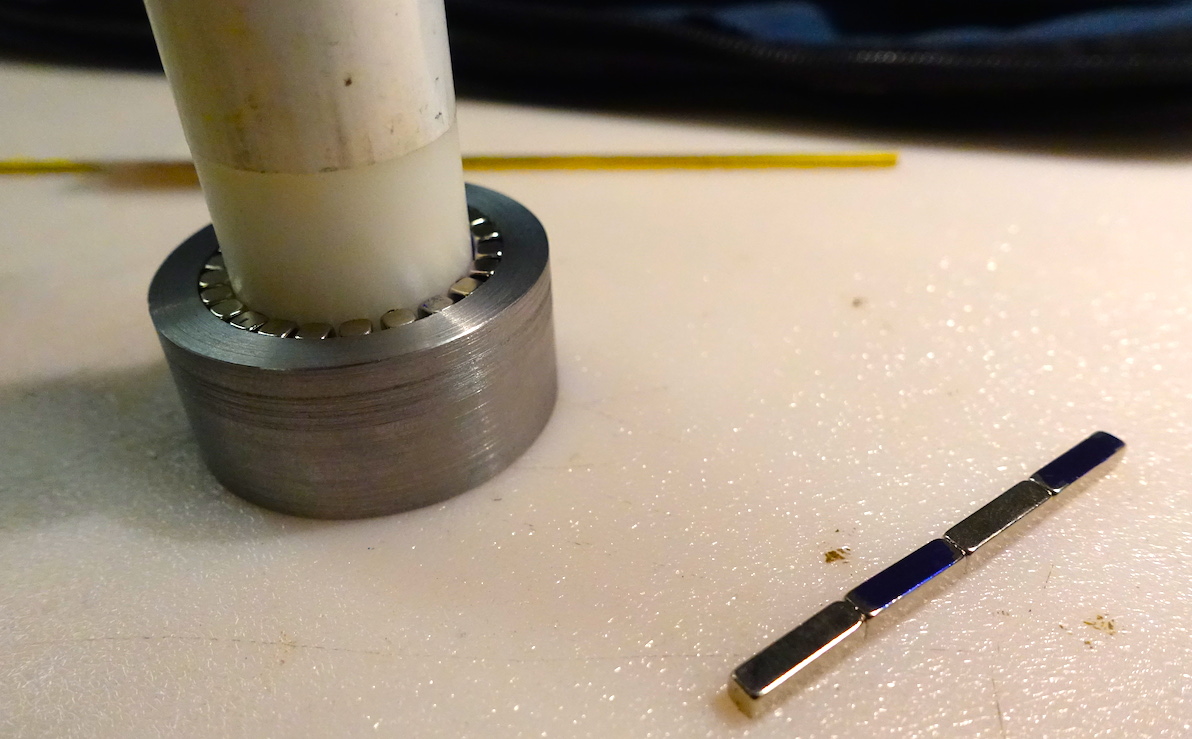
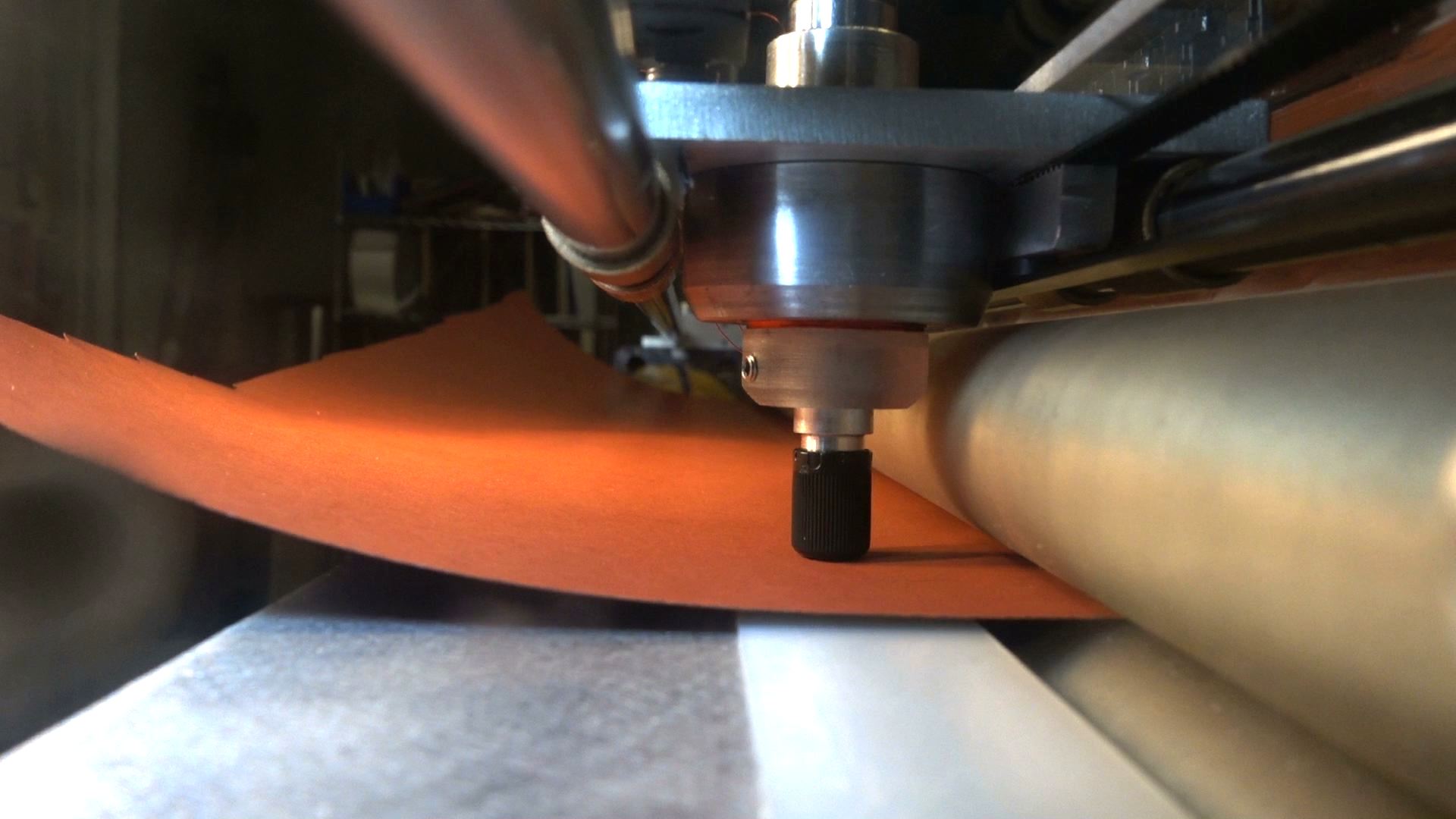
As a baseline, I made a voice coil to drive a Roland vinyl cutter knife. This device is a much larger stroke than necessary for oscillatory cutting, but it's useful on a CNC device because it allows us to move the knife up out of the way for traversing.
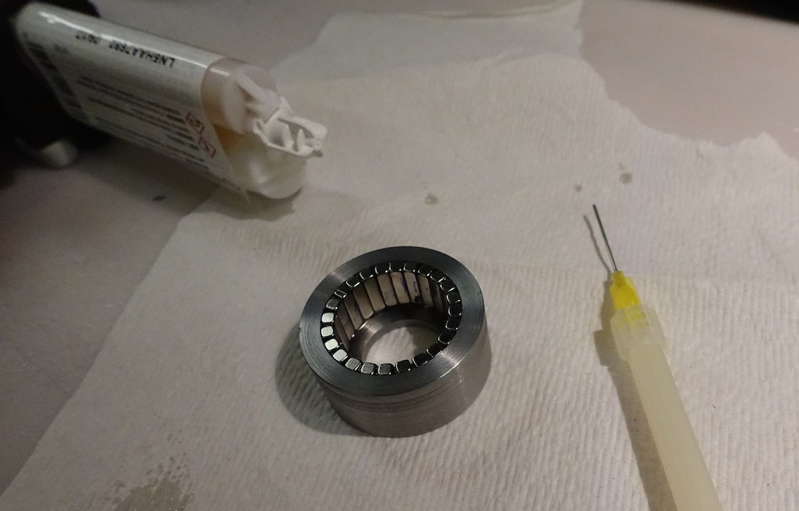
To spec the magnet wire diameter for the bobbin, I looked at flux, current, and number of turns as a function of the wire diameter. Too much current and the device overheats, too little flux and we don't have enough force, and too many turns is hard to make.
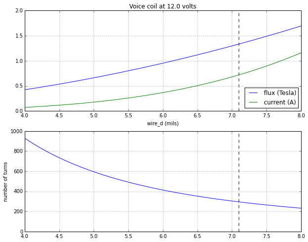
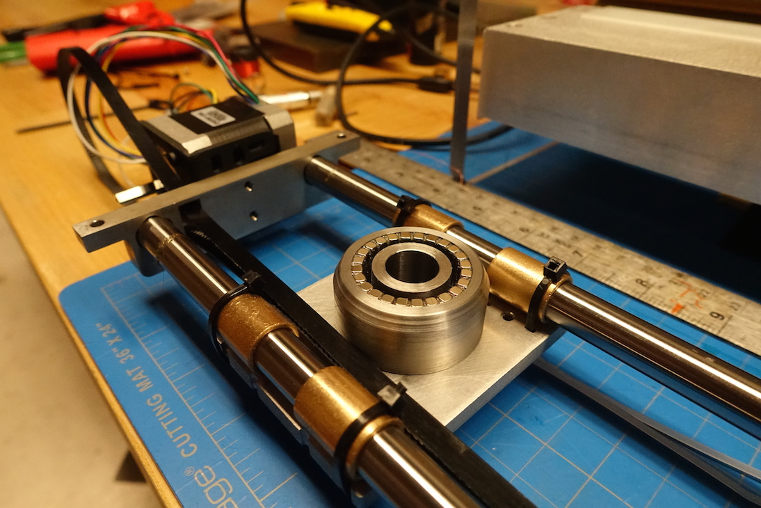
With these graphs in mind, I chose around 400 turns over 1/2" of length and 1" diameter for my coil, 3D printed a bobbin, and wound it on the coil winder with 30 AWG wire.
Here's a video of the operation:
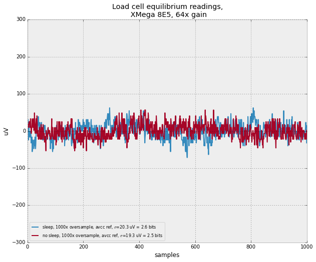
To get feedback about force produced by any of the oscillating knife mechanisms, I need force measurement. I bought some cheap $7 load cells, and used the 64x gain on the xmega 8e5 (rather than a dedicated amp). I've never done this much amplification with the microcontroller along, and I was pleased with the results:
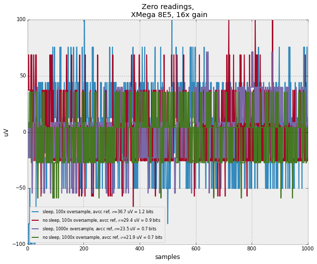
To get a better idea of the limits of the xmega's adc, I started measuring the ENOB ("effective number of bits"). This is two differential input pins tied together outside the MCU. Below are results with 1000 samples averaged. We can see this easily falls below a bit of error with 16x gain. Impressive! I see no difference between sleeping and not sleeping during measurement, leading me to suspect the noise I'm seeing is on the AVCC line or on the differential pin loop. I'd like to try it again with a filter on the AVCC line. Also, I want to mod out for time dependence (no oversampling, or measure enob / second, or something).
The coolest version of this project would include imaging three dimensional mode shapes of an oscillating blade at tens of kilohertz. I'm lusting after this camera which at 18kfps gets some of the way there. To get the rest of the way there, I'd need to use its genlocking capabilities to undersample the periodic movements of the blade. The shortest shutter speed of the camera is 1/200000, so that places a limit on the highest undersampled frame rate under continuous lighting conditions. Say we wanted 8 frames per period, that means an upper limit of 25 kfps -- not much higher than the flat out frame rate.
To get around this limit, we need to strobe the lights. After researching this for a minute, it seems that this world is really shifting to LEDs. Even though the light intensity is usually lower than a flash bulb, pulses can be shorter, lower voltages are required, less heat is generated, etc. To get a handle on this, I set up an experiment to see how much we can overdrive a power LED for a very short time. I bought Golden Dragon LEDs, rated for 1 amp continous, and a couple visible range photodiodes with response times around 10 ns.
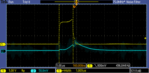
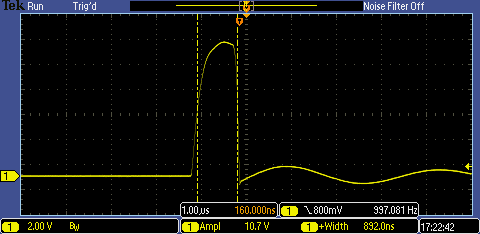
The photodiode pushes current through a small resistor (~1 Ohm) and generates a voltage that we measure to determine the length of the light pulse. The photodiode system has a response time, but we can provide a worst case bound on the light pulse using it. In the images above, I pulsed 10 amps through the LED using an Xmega timer for 1 us. The duty cycle is extremely low (1 part in 1k), but to the naked eye it appears reasonably lit.
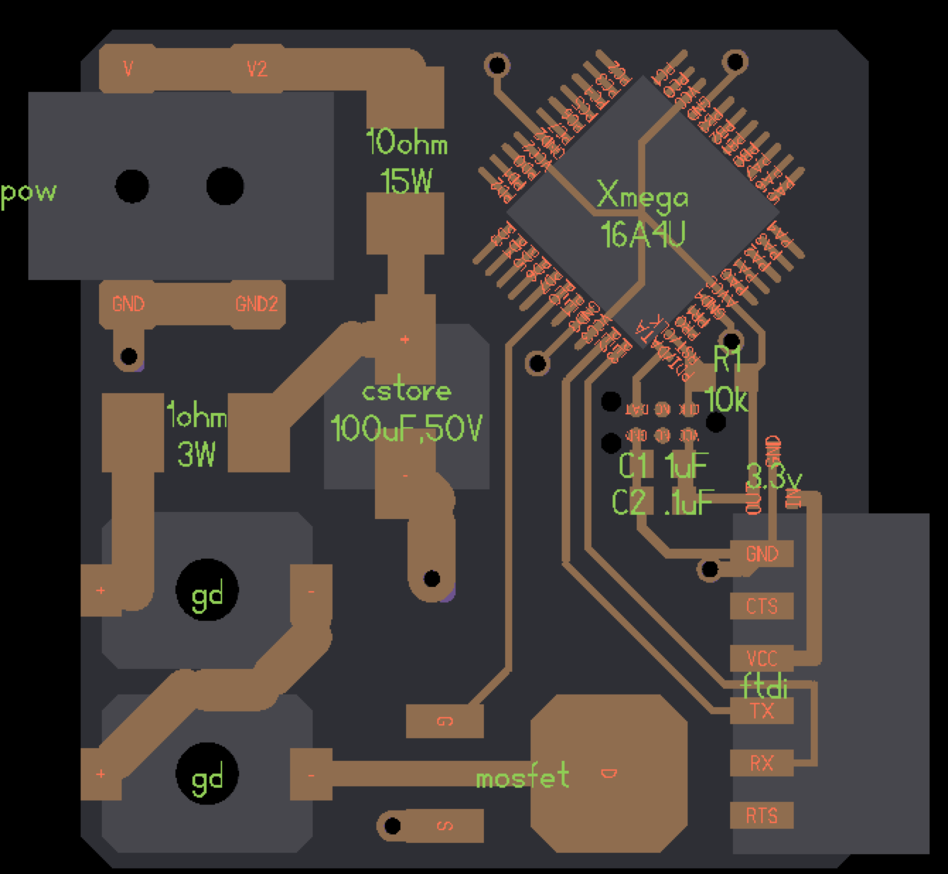
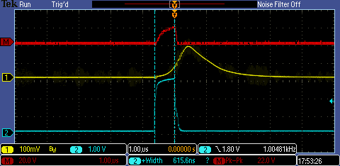
My current peaks were limited by my power supply, but I did a quick redesign to use a fat capacitor to pulse higher currents. The two designs are shown above. I tested this board, and the scope traces are below. Blue is the control signal pulse (~600 ns). Yellow is the photodiode-resistor voltage. Red is the current through the LEDs, topping out around 22 amps (measured using the oscilloscope's math function on two input signals -- that's why it's a little fuzzy). This is certainly more current than before, but I did forget to take the increased ESR of my beefier 220uF aluminum capacitor into account. I should either switch back to a smaller cap (we're not nearly draining it in these short pulses), or reduce the current limiting resistor in my circuit.
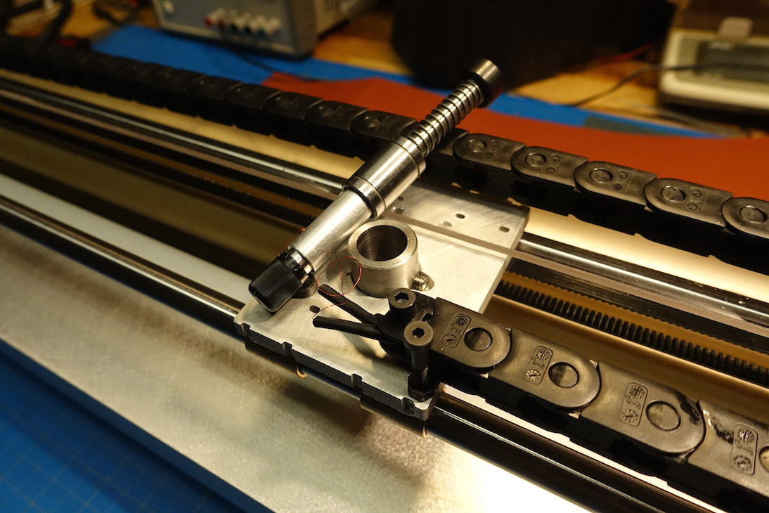
I also got an xmega controller working for my homemade voice coil roland knife. Here it is doing some oscillating cutting at ~150 Hz, shot at 1000 fps. The VCA doesn't quite warrant stroboscopy, but I can't wait to make the piezo version 1000x faster and image it with motion magnification.
To simulate capacitive load cell designs, I wrote a simple electrostatics solver, based on this great article by James Nagel. We can start from Gauss' law, written with a spatially varying relative permittivity: $$ \nabla \cdot \left( \epsilon(\mathbf{r}) E(\mathbf{r}) \right) = -\frac{\rho(\mathbf{r})}{\epsilon_0} $$ where $\mathbf{r}$ is a point in space. Written in terms of a voltage potential $V$, we have $$ \nabla \cdot \left( \epsilon(\mathbf{r}) \nabla V(\mathbf{r}) \right)= -\frac{\rho(\mathbf{r})}{\epsilon_0} $$ If the permittivity is constant, we have a familiar Poisson equation: $$ \nabla^2 V(\mathbf{r})= -\frac{\rho(\mathbf{r})}{\epsilon\epsilon_0} $$ which we can easily solve with finite difference methods to get the potential from a charge distribution. We can take the gradient of this potential to get the electric field. Nagel shows a neat way to similarly solve the non-constant permittivity case by first writing the equation in the integral form: $$ \iint_{\Omega_{ij}} \nabla \cdot \left( \epsilon(\mathbf{r}) \nabla V(\mathbf{r}) \right) d\Omega = -\frac{Q_{ij}}{\epsilon_0} $$ where $\Omega_{ij}$ is the square region around the grid point $(i,j)$ and $Q_{ij}$ is the charge contained at the grid point. We can eliminate one of the differential operators by applying the divergence theorem to the left side: $$ \iint_{\Omega_{ij}} \nabla \cdot \left( \epsilon(\mathbf{r}) \nabla V(\mathbf{r}) \right) d\Omega = \oint_{C_{ij}} \epsilon(\mathbf{r}) \nabla V(\mathbf{r}) \cdot d\mathbf{n} = \oint_{C_{ij}} \epsilon(\mathbf{r}) \left( \frac{\partial}{\partial x} V(\mathbf{r}) \hat{\textbf{x}} + \frac{\partial}{\partial y} V(\mathbf{r}) \hat{\textbf{y}} \right) \cdot d\mathbf{n} $$ in two dimensions. If we define the discretization of permittivity at coordinates offset from the original grid coordinates, and break up the contour integral into four straight sections, this expression becomes easy to approximate with central differences. We are left with $$ -a_0 V(i,j) + a_1 V(i+1,j) + a_2 V(i,j+1) + a_3 V(i-1,j) + a_4 V(i,j-1) = - \frac{Q(i,j)}{\epsilon_0}$$ where $$ a_0 = \epsilon(i,j) + \epsilon(i-1,j) + \epsilon(i,j-1) + \epsilon(i-1,j-1) $$ $$ a_1 = \frac{1}{2}\left( \epsilon(i,j) + \epsilon(i,j-1) \right)$$ $$ a_2 = \frac{1}{2}\left( \epsilon(i,j) + \epsilon(i-1,j) \right)$$ $$ a_3 = \frac{1}{2}\left( \epsilon(i-1,j-1) + \epsilon(i-1,j) \right)$$ $$ a_4 = \frac{1}{2}\left( \epsilon(i,j-1) + \epsilon(i-1,j-1) \right)$$ This stencil equation has precisely the same form as would come from the classic Poisson equation using finite differences, only now with spatially varying permittivity. As such it can be easily solved using successive overrelaxation, or a sparse matrix solver. These values for $a_i$ can be precomputed if the distribution of permittivity remains constant. I implemented a version of this using Numpy for the stencil operations and successive overrelaxation as the solver. You can take a look at the (slow, dirty) code here.
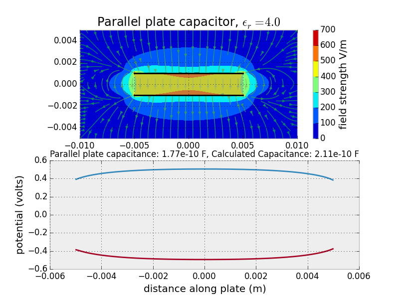
Just as a sanity check, I first implemented a parallel plate capacitor to check agreement with the formula for capacitance that we derived by considering a section of a infinite capacitor. The simulation produces reasonable agreement, and it is interesting to observe the fringing effects that account for the difference.
Next, I investigated two designs for capacitive load cells. In the first, a dialectric material moves in response to a load. This is similar to the notebook in Neil's favorite TXRX video. It is also the mechanism used in this article, as mentioned in the overview.
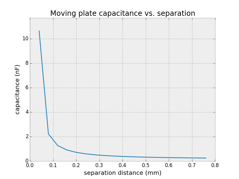

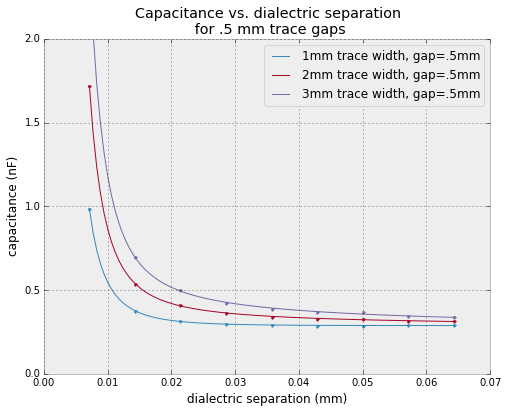
To get a good response with moving dialectric, we've got to bring the separation closer than I think is feasible to accurately control.
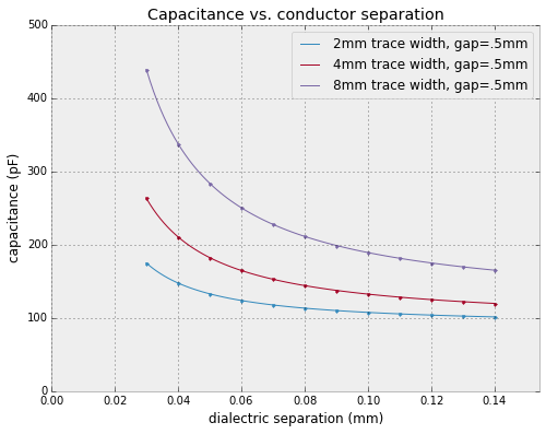
A nice medium ground could be a moving conductor. We can simulate this in the electrostatics solver as written in one of two hacky ways. First, as permittivity goes to infinity, the behavior of a dialectric becomes that of a conductor. Unfortunately, increasing permittivity slows down the successive overrelaxation solver, so this isn't ideal. We could also place mirror charges by hand that enforce the E=0 condition inside a conductor. This isn't technically accurate, but it's easy.
Settled on moving conductor, I designed a quick pcb to test. I didn't think to hard, just maximized electrode area exposed to the moving conductor and tried to keep sensor traces short. I didn't place the large resistors as in Neil's TXRX board (mostly because I forgot, but also I'm not 100% certain they are necessary here). I sent pulse to the central transmit pad and measured after 20 microseconds. Without a lot of tweaking, this worked pretty well! I set up the ADC in differential mode, taking opposing pads as positive and negative inputs and apply 16x gain (a value that produced reasonably stable results).

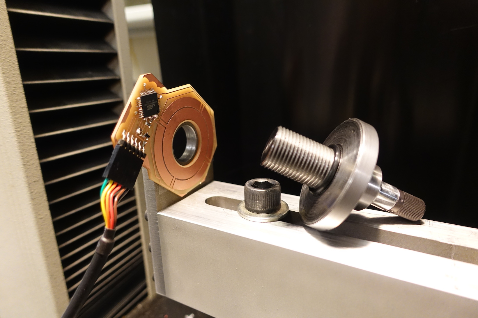
By preloading my thumb nut, I can adjust the gap and stiffness (yes, they are correlated...). I was very satisfied in the stiffness I could put on the load cell while still measuring forces accurately. Below, is the first test I did, showing about 5 microns deflection at the knife tip per Newton of applied force.
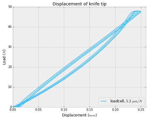
I did a few cycles, ramping load to 50N (the design spec). The capacitance value tracked very well! The load cell itself is a little hysteretic -- I attribute this to using rubber O-rings. As the next test, I'd like to use PTFE instead.
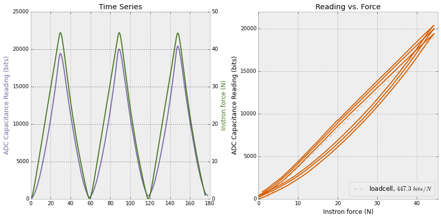
Within the variation of the measurement, this looks like we can measure grams of tangential force. Better than I'd hoped!
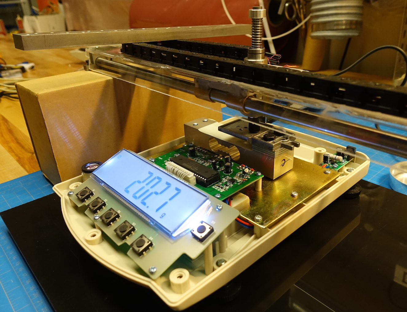
To determine force and displacement of the voice coil actuator itself, I cobbled together a simple force measurement rig using a precision balance with a bidirectional RS-232 port. I can send a few simple commands (TARE, REQUEST_WEIGHT, etc.) from a master script that is also sending commands to my voice coil driver board. Here is a stripped down python script with just the scale interface commands.
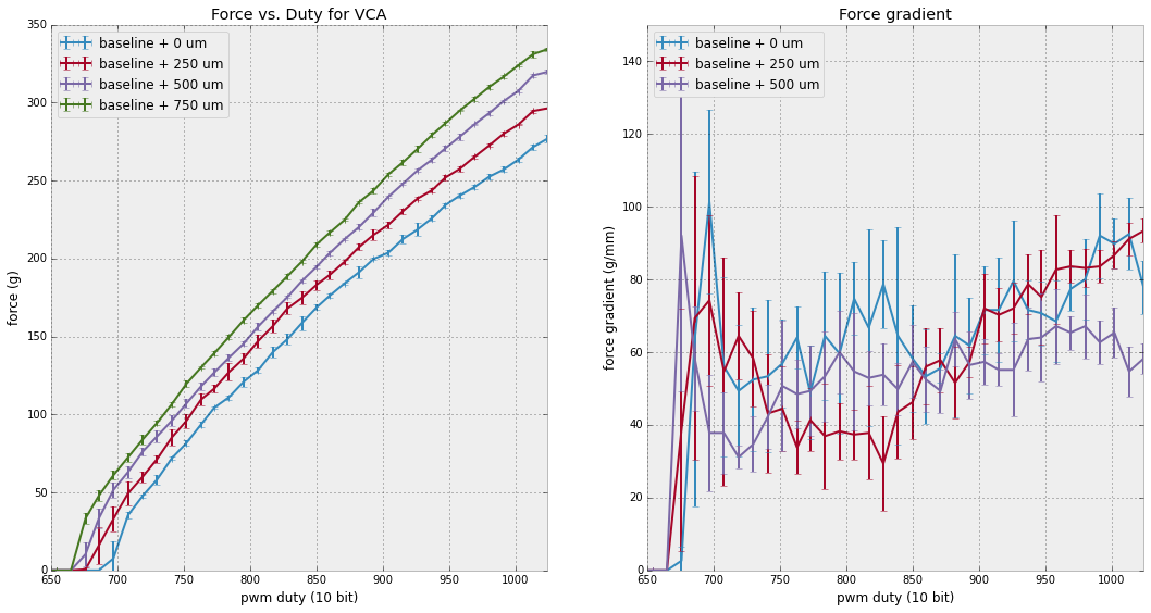
Above at left is a graph of force vs. duty, as measured by the scale. The results are very repeatable (error bars shown for three runs each), except for the zero force point (a function of overcoming friction in the VCA, and not relevant to operating conditions). I repeated the measurement, offsetting the position of measurement by putting 250 um shims underneigth the scale. We can see that as the measurement point increases (the coil is more retracted), the force produced for a given duty cycle increases. The reason for this is twofold: First, more of the coil remains in the region of high magnetic field, so more of the coil flux is involved in the production of force. Second, the spring return is more relaxed, producing less counteracting force.
Together this produces a surprising result -- the relationship between force and duty is a very sensitive measurement of displacement. The graph at right shows the sensitivity of the measurement as a function of duty. In the operating range, we see roughly 60-80 grams per mm of displacement. Thus, if we can measure force on the actuator to 1 gram precision, we can determine displacement to 12-16 um. This is all at rest, of course, without any tangential forces to confound the measurement.
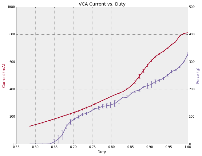
Next, I set up a current measurement for the voice coil by measuring the voltage across a sense resistor (.25 Ohms) at the bottom of my H-bridge (A4953, measuring the sense pin). Originally, I was getting strange measurements from this, so I set up my measurement timing as a function of the PWM pulse edges. These PWM pulses are generated by a Timer/Counter on my XMega (TCC0) in waveform generation mode, where the Compare register sets the duty cycle (see AVR1306 for more details). To synchronize my measurement, I simply start another Timer/Counter (TCC1) at the same time, running normal mode. On overflow of this timer, I start an ADC conversion. The period of this timer determines how many measurements take place during a single PWM cycle, and how many pulses to undersample over. $$n = \frac{p_{\text{pwm}}}{ gcd( p_{\text{pwm}}, p_{\text{adc}} ) }$$ where $n$ is the number of samples over one period, $p_{\text{pwm}}$ is the period of the PWM signal, and $p_{\text{adc}}$ is the adc sampling period. In practice, we can set the PWM period to be a power of two, pick a desired number $n=2^m$ of samples per pwm period (say 64), and set the adc sampling frequency to $q p_{\text{pwm}}/2^m$ where $q$ is any odd number which scales the adc sampling rate to be achievable with the xmega. In this way, we are effectively integrating the current over the PWM cycle.
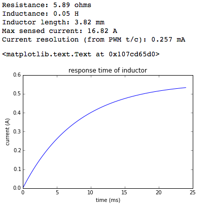
I want to experiment with measuring the time constant of the current waveform. This should depend on the inductance (as roughly R/L), which should be a function of displacement directly (overlap of the coil with the region of high permeability is a linear function of displacement).
As is usually the case, I could just focus on one project. I did some work this semester investigating the tradeoffs in cost, complexity, and accuracy for non-contact electric power measurement devices. I want to measure power consumption of common appliances without any conductor to conductor contact -- this increases a lot of safety precautions that are required. I'd also like to be as unobtrusive and cheap as possible.
Two main approaches: 1) direct measurement of current transformer, or 2) Hall effect measurement in current transformer core gap. Approach one is shown first, where I've wound magnet wire around one half of a clamp-on ferrite bead. This a measureable signal, and even opens the possibility to energy harvesting, but it must be rather large.
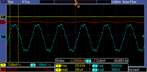
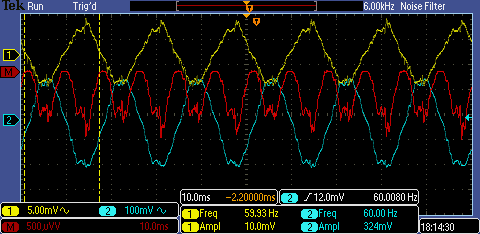
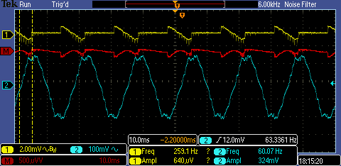
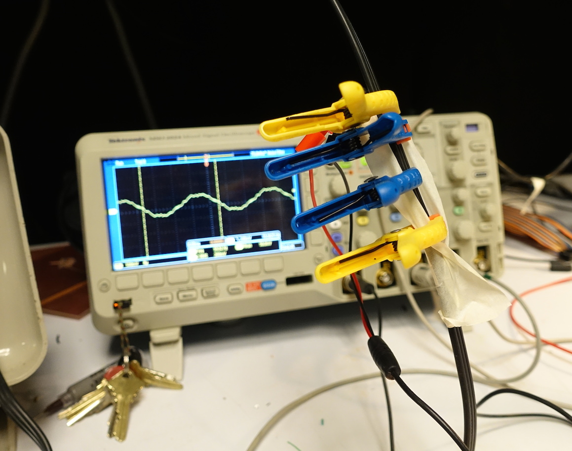
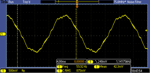
It's important to note that we can't just measure current to compute watts. In AC lines, the phase lead or lag is a function of the load type. To truly calculate power, we would compute an integral of the current times the voltage over time. Below we show some scope traces from the current transformer above (shown in yellow). The blue trace is proportional to the voltage, measured capacitively by placing the scope probe close to the hot wire. The red is the product of the two, the instantaneous power. The first image shows no current draw -- voltage is a period function provided by the grid but no current is drawn, and hence no power dissipated. The middle image is driving a large resistive load (a soldering heat gun). For the large resistive load, the voltage and power are in phase with each other because the load is not reactive (an astute reader will notice that my polarity is reversed...and hence the product isn't actually correct. doh!). The right image shows just the fan of the heat gun -- this load looks switched, so computing an integral would be necessary for measuring the power draw.
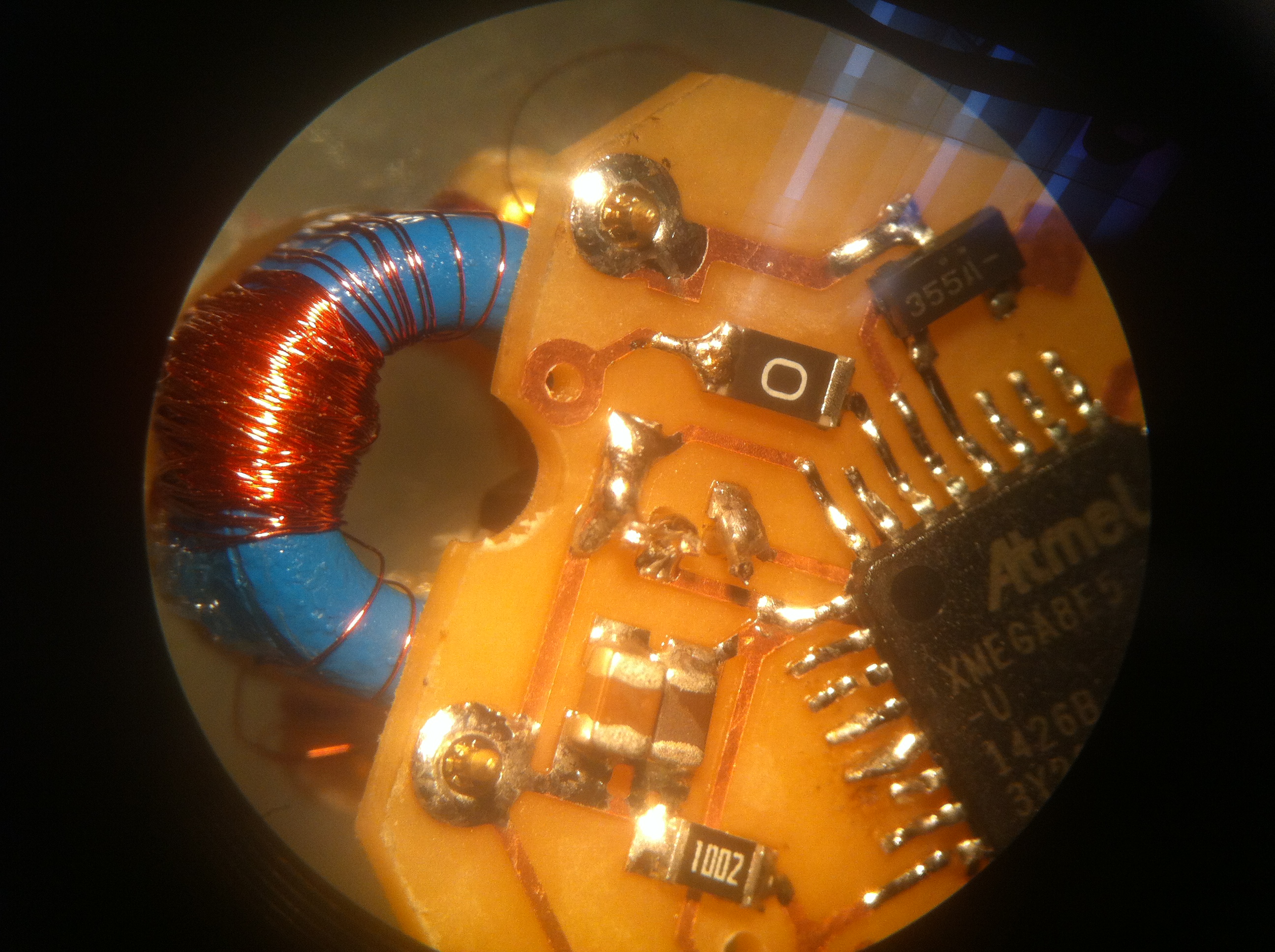
Given my design spec of being nonobtrusive, I looked into a less direct but more compact current measurement using a hall effect sensor. We put the sensor in a gap in a flux concetrator and measure the flux (which is directly proportional to current). Further, we can make the measurement more reliable and linear by wrapping a secondary coil around the flux concentrator and driving the measured flux to zero. This way, we are less reliant on factors like permeability and temperature in our measurement. The image below shows a prototype board for this measurement. I found some nice pin receptacle connectors through Mill Max for attaching the flux concentrator (ferrite toroid).
I haven't tested this board yet, but I'm excited to try it out. Given the response time of the inductor (estimated below), I think I'll be able to get away with a mosfet for pulsing the secondary (rather than a large op amp).
On another track, I picked back up some previous work on powering these devices by harvesting energy from the ac line being measured. Previously, I had made current transformers to pull energy from the magnetic field of the wire. This worked well, but required a large wound ferrite. To try to eliminate this, I decided to investigate pulling energy from the electric field instead. This approach could have a number of advantages, including the fact that the device can pull power even if no current is flowing through the cord. I found one paper on this, where they simply wrap an mains cord in aluminum foil and couple through earth ground. One difference between this and what I was thinking, is that we may be able to do better if we couple between two electrodes near the live and neutral wires.
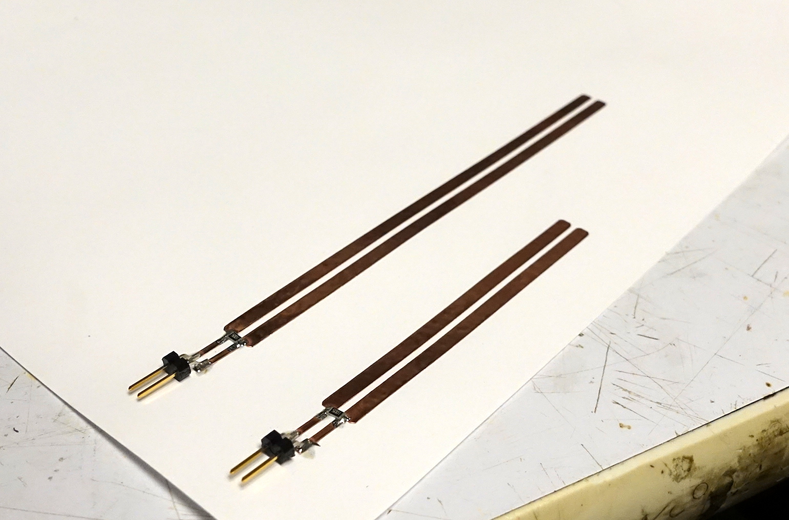
As a simple test, I vinyl cut a pair of electrode strips approximately the width of the insulation of an AC power cord. I connected them with a large resistor (on the order of a megaohm). Then, I laid them onto a power cord to capacatively couple with the conductors inside.
I was suprised that without thinking too much about this, I saw potentials around a volt across a 1 MOhm resistor, corresponding to around a microamp dissipated. This makes me think there could be potential here. I wonder if we can turn this device into an electromagnetically short antenna, put a matching network on it, and extract more power. This would require an LC circuit that resonates at 60Hz (verrry slow). This means the square root of the product of the inductance and capacitance is one over 120 times pi. The capacitance of my electrodes is roughly 10 pF (based on parallel plate approximation, and roughly confirmed by matching experiment to spice simulation).
Another direction this project could go is sensing current passing through a cord without isolating one of the conductors to pass through a flux guide. This is akin to usion only the Biot Savart law to measure current, instead of Gauss' law. I wanted to get an idea of the orders of magnitude involved, so I implemented a very simple simulation that numerically integrates the magnetic field contributions from an opposing pair of current carrying conductors. To start, I wanted to see what was possible without using a flux guide. A screenshot is shown below:
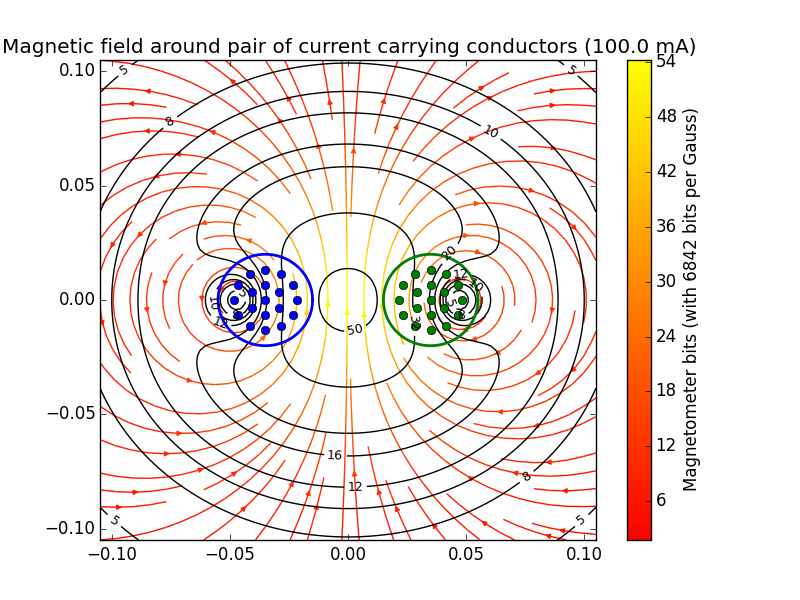
This shows that using a cheap digital magnetometer, it should be possible (ableit difficult) to measure the current. I'm worried these measurements are near the noise floor of the device, so I next turned to flux guides that would be simple to implement. Doing a similar simulation using flux guides requires a full magnetostatics FEA solver, so I'll work on this soon.
If we're thinking of using flux guides with hall effect sensors, the geometry starts to get tricky, because we would like to insert the hall effect sensors into gaps in the flux guide. A more elegant approach would be to use secondary windings aranged along the flux guide. This way the guide stays in one piece, and the field stays more symmetric (easier to invert). I tested this with a single seconary of a few turns on a ferrite toroid, running a conductor pair through the toroid and disippating current through a resistive load across the conductors. I thought I'd be able to see some signal proportional to the current and see the anisotopy of the magnetic dipole-like field, but the results were too noisy to see anything. I'll think more about why this is and try again.
As a hailmary, I wonder about using a similar "arts and crafts" approach as the electrostatic energy harvester above to this problem, again just increasing the shared cross sectional area between input and output by moving to a low mass sensor (paper and copper film). Maybe we could use magnetic tape from a cassette to form a flux guide? How thick is that coating on them anyway?
A paper from MIT a few months ago peaked my interest -- it described a novel desalination technique called shock electrodialysis. Based on my reading, it gets around the biggest headache of conventional desalination (clogging filters) by using electric shock waves in a porous media to do bulk separation. The implementation given is very much a bench prototype and is very inefficient. I'd love to understand this technique more and build a prototype.
The Phree is the best pen tracking system I've seen. It uses a "3d laser interferometry" technique, detailed in this patent. I have no desire for the product they are offering, but I'd love a responsive and cheap pen tracking system. It would be fun to make an AVR version of this device.