What am I aiming to do ?
Investigation space: Manipulating and controlling things on a small scale (1 um to 100 um)
Possible Directions I looked at:
-
If a microgripper such as this MEMS microgripper for gripping 100 micron objects were to be made of Mechanical and Electronic digital bricks (Will's digital material), what are the overhead in terms of real estate, material and fabrication cost and power requirements ?
-
How to create a Switchable mechanical connection with tunable attraction force for modular robots such as Ara's Robot Pebbles ?
Other things related to robotic pebbels: How to increase the force of attraction between two robotic blocks to be able to resist shearing and rotation. This would be required when robotic pebbles are scaled to assemble into 3d shapes. Can we use Van der Wall's adhesion or some sort of mechanical interlock or electrostatic force ?
-
As robotic pebbles are scaled down, how far does the electropermanent magnets scale ? Electrostatic field and forces are limited by deielctric breakdown and magnetic field is limited by scaling of coils and magnetization. In what regime does electrostatic connection take over electropermanent magnet ?
Final Proposal
SRI made these really cute tiny robots that collectively assemble materials to build electrical and mechanical structures. If these were to be scaled down, how do we do that ? What physical forces can be used to control the maneuver of the robots?
Given an array of addressable coplanar electrodes can we use elctric field to maneuver these robots? How can we use them to manipulate a block of neutral untethered material ?background and prior art for the project
- W. Trimmer and R. Jebens, "Actuators for micro robots," Robotics and Automation, 1989. Proceedings., 1989 IEEE International Conference on, Scottsdale, AZ, 1989, pp. 1547-1552 vol.3.
- Peirs, Jan, Dominiek Reynaerts, and Hendrik Van Brussel. "Scale effects and thermal considerations for micro-actuators." Robotics and Automation, 1998. Proceedings. 1998 IEEE International Conference on. Vol. 2. IEEE, 1998.
- Abbott, Jake J., et al. "Modeling magnetic torque and force for controlled manipulation of soft-magnetic bodies." Robotics, IEEE Transactions on 23.6 (2007): 1247-1252.
- Wautelet, Michel. "Scaling laws in the macro-, micro-and nanoworlds." European Journal of Physics 22.6 (2001): 601.
- Cugat, Orphee, Jerome Delamare, and Gilbert Reyne. "Magnetic micro-actuators and systems (MAGMAS)." Magnetics, IEEE Transactions on 39.6 (2003): 3607-3612.
- Diller, Eric, et al. "Control of multiple heterogeneous magnetic microrobots in two dimensions on nonspecialized surfaces." Robotics, IEEE Transactions on 28.1 (2012): 172-182.
- Diller, Eric, et al. "Six-degrees-of-freedom remote actuation of magnetic microrobots." Robotics science and systems. 2014.
- Donald, Bruce R., et al. "An untethered, electrostatic, globally controllable MEMS micro-robot." Microelectromechanical Systems, Journal of 15.1 (2006): 1-15.
- Multiple magnetic microrobot control using electrostatic anchoring. Chytra Pawashe1, Steven Floyd1 and Metin Sitti.
- The Motion and Precipitation of Suspensoids in Divergent Electric Fields. Herbert A. Pohl.
- Some Effects of Nonuniform Fields on Dielectrics. Herbert A. Pohl.
- Breguet, Jean-Marc, et al. "A review on actuation principls for few cubic millimeter sized mobile micro-robots." Proceedings of the 10th International Conference on New Actuators (Actuator 2006). No. LSRO-CONF-2007-007. 2006.
Progress

Manipulating objects at micrometer scale has interesting applications such as assembling electrical and mechanical systems at small-scale. Manipulation in this context would mean gripping and transporting. One way to move micrometer scale objects between known positions is to use untethered microrobots controlled through an external electrostatic field. The microrobot in this case is a block of isotropic dielectric. In the scope of this project I will be looking at the transportation of materials in 1μm to 100μm scale.
What questions am I asking ?
- What governs forces on a neutral block of material (1 um - 10 um) in an electric field?
- How does a dielectric block expereince forces in an electric field ?
- What is the magnitude of force required to move a 10 micron block of Silicon dioxide on a grid of electrodes of similar magnitude ?
- How does the force scale with the dimension of the dielectric block and voltage applied across the electrodes?
- What geometry of electrodes can move the dielectric on a XY plane ?
- At what speeds can this block be moved around ?
1. What governs the forces on a neutral block of material in an electric field ?
2. Force on a dielectric in a non-uniform electric field
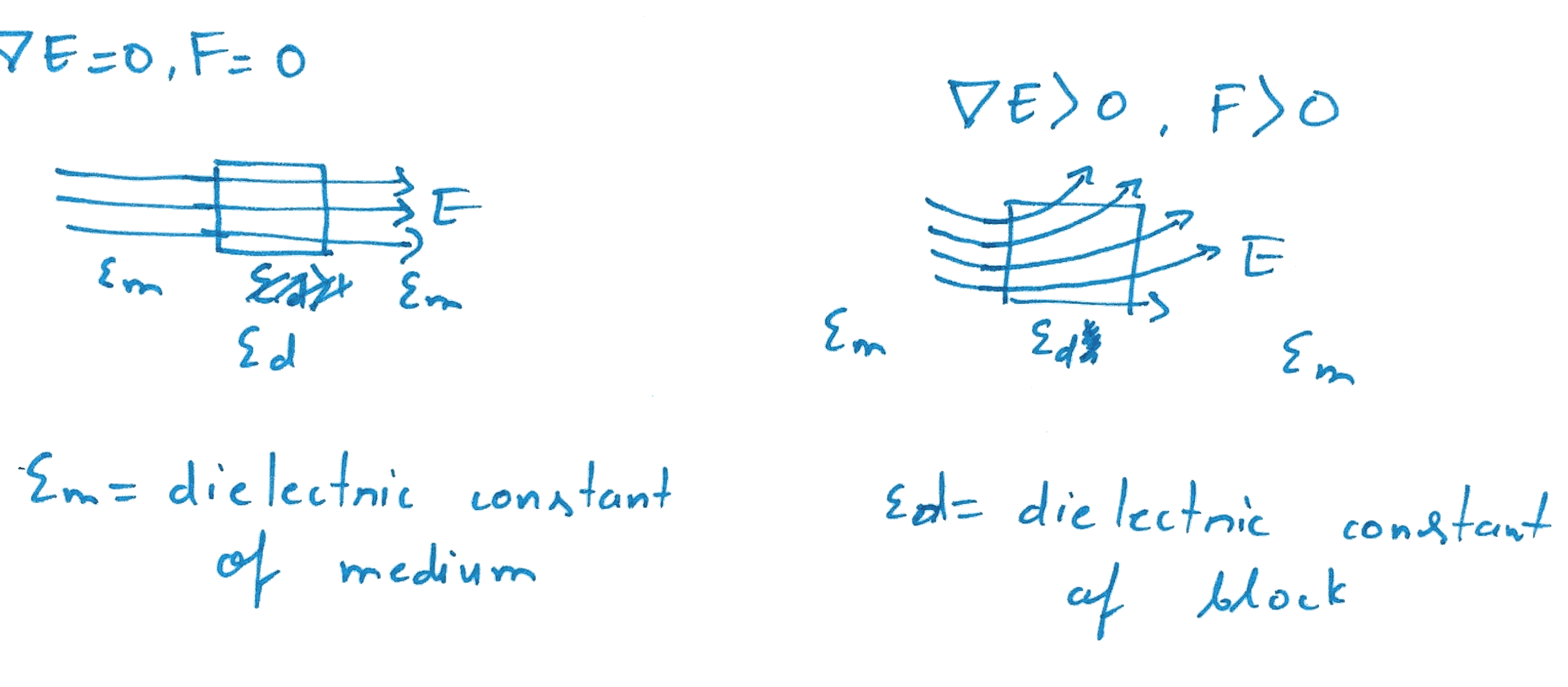

A dielectric when suspended in an electric field undergoes polarization. The dipoles induced in the block experience forces due to the field. If the field was to be uniform (∇E = 0), with uniform polarization, the force experienced by the dielectric averages to zero. In a non-uniform electric field (∇E > 0), a block of dielectric expereinces a net force due to finite charge density. The net force expereinced by the block depends on:
- Dielectric contant of the block, εd
- Dielectric constant of the medium surroudning the block, εm
- Gradient of electric field ∇E
- Frequency of applied field
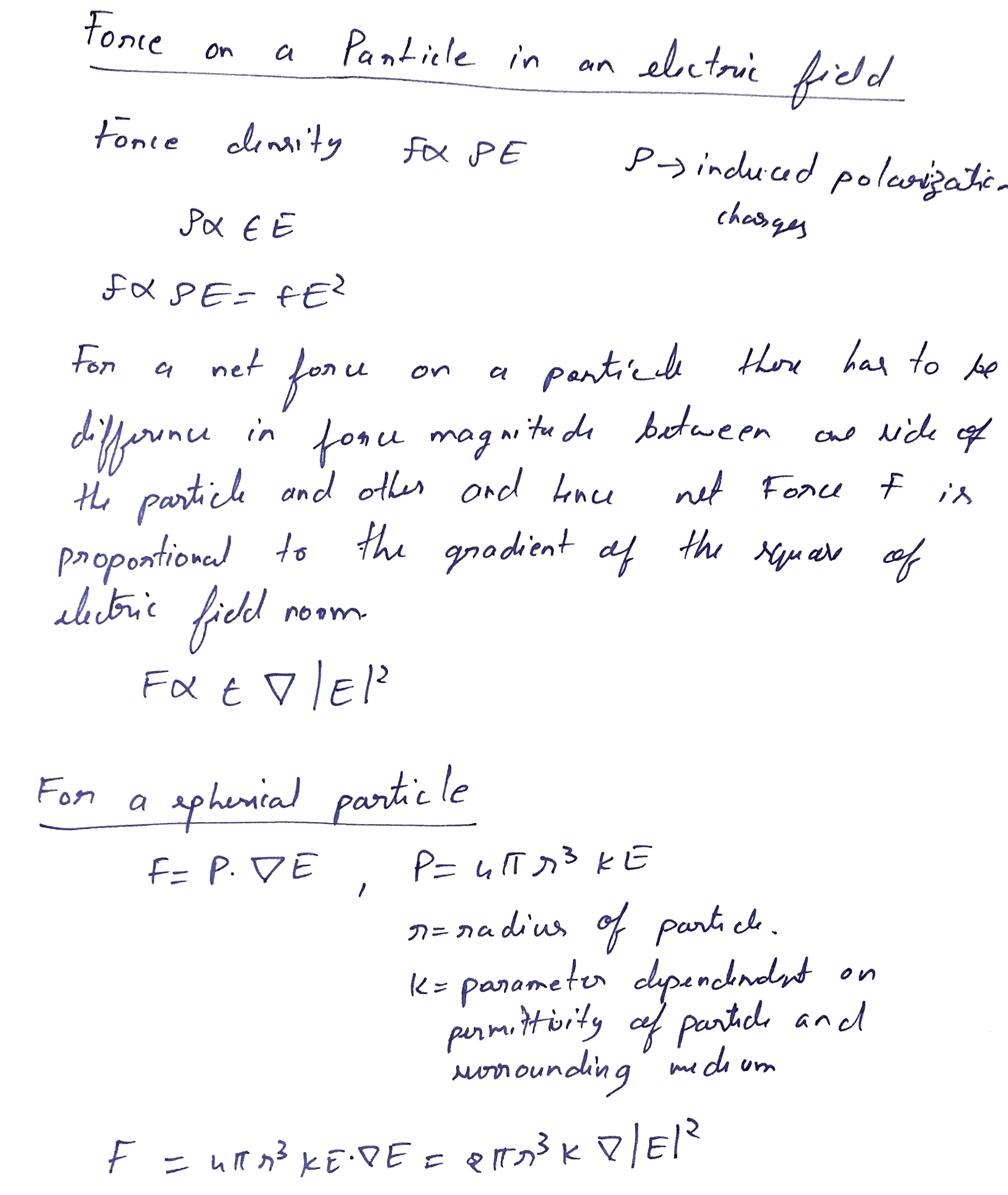
For a dielectric particle, net force is given by
$$ F = P\cdot \nabla E$$
For a spherical particle of radius r,
$$ P = 4 * Pi * r^3*k*E$$
where k is a complex quantity that depends on the permittivity of the dielectric and the surrounding medium and E is the electric field. Combining these we get,
$$ F= 2 * Pi * r^3*k*\nabla |E^2|$$
The 2*Pi*r3 can be seen as shape factor, and hence more generically the force is prpotional to volume of the particle and gradient of the suqare of the field norm
$$ F \alpha Volume* Dielectric Constant* \nabla |E^2|$$
Dielectric breakdown with micron separation and Field Gradient
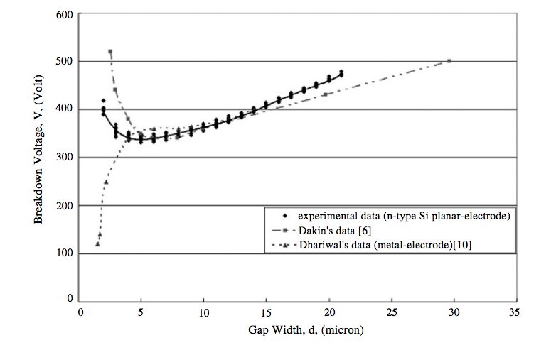
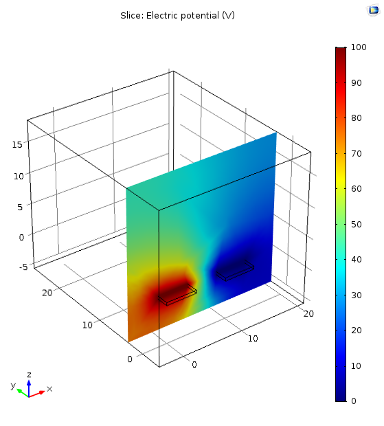
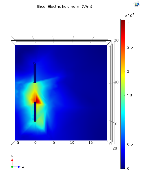
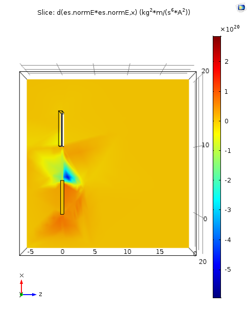
With Silicon dioxide as the dielectric material and static field, the dielectric of the target block remains constant. For this project I will be looking at the effect of scaling of object volume and field gradient. The next question would be to find out the field gradients that can be achieved at micron sepration between electrodes. For a 5-10 um separation between electrodes the maximum voltage before air breaksdown is 300V. See this reference more details.
For a 10um separation between the electrodes and 1V between the electrodes, from COMSOL simulation, the order of magnitude of the gradient is $$ V=1 V, \nabla |E^2| = 10\exp15 V^2/m^3 $$ $$ V=100 V, \nabla |E^2| = 10\exp19 V^2/m^3 $$
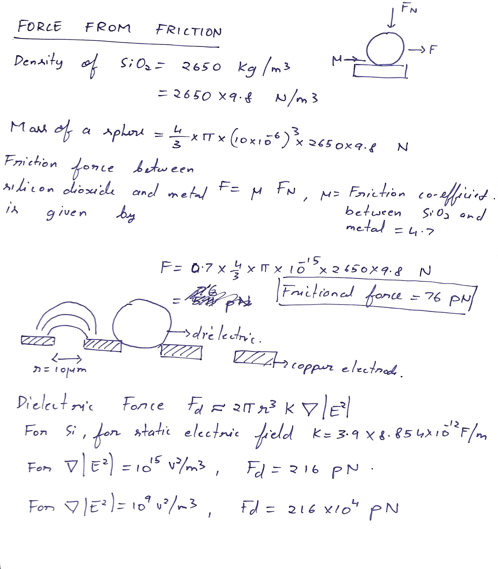
3. Back of the envelope calcualtion of forces
Back of the enevlope calculations (see image below) give us the mass of a 10 micron silicon dioxide particle to be 100pN and the static friction experienced by it to be of similar order (75pN). In order to move the object on an horizontal plane, we need to over come the static friction between Silicon dioxide and metal electrode. For particle levitation the force generated should exceed the effect of gravity and hence the weight ~ 100pN. At 10 micron electrode separation and at a potential difference of 1V, the dielectric force is comparable with the static friction, wheres when the voltage is increased to 100V, the dielectric fields is greater by an order of magnitude 4.| Weight of 10um SiO2 particle | Static Friction Foec | Dielectric Force (Voltage between two electrodes = 1V ) | Dielectric Force (Voltage between two electrodes = 100V ) |
|---|---|---|---|
| 100pN | 75pN | 216pN | 216 X 10e4 pN |
4. Scaling of size of the particle to be manipulated. Order of magnitude plots.
The scaling of the dielectric object that is being manipulated and the Polarization force generated is dependent on several factors:
-
Nature of manipulation
Manipulating the object would involve positioning on a horizontal XY plane and even levitation in Z direction. These manipulations depend on the design of the next 3 paramaters -- geometry of electrodes, dielectric constant of material and field gradient. Within the scope of this project I would be focussing on moving the object from Point A to Point B on an horizontal plane in the X-direction and possibly then extend this to XY-plane.
-
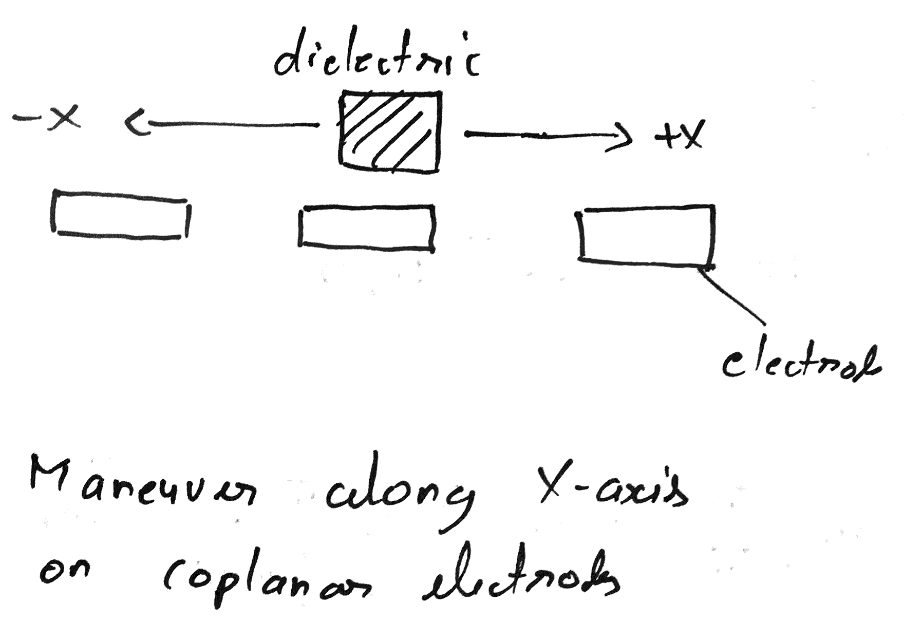
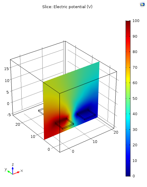
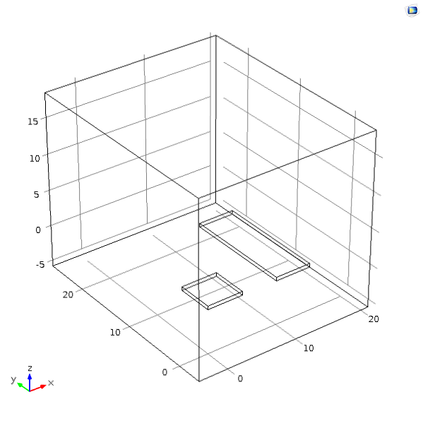
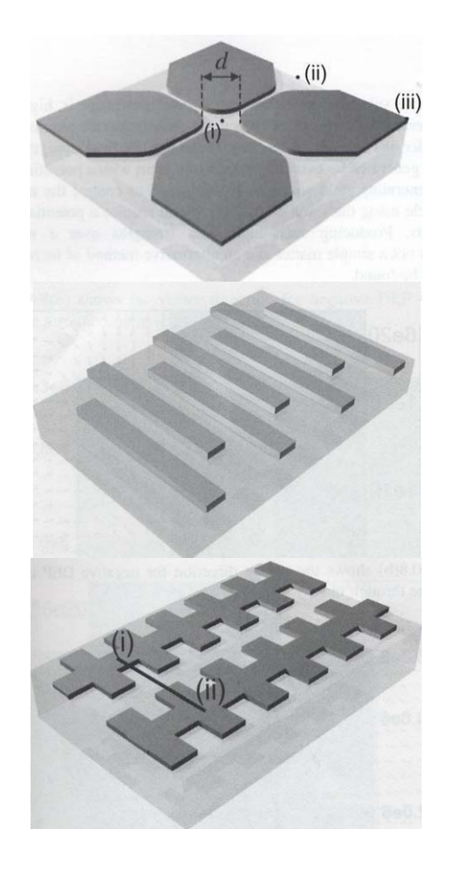
Geometry of the electrodes and object
Electrodes for manipulating the object can have various geometry. Some of the common ones found in the literature are parallel finger, comb-like interdigitated, semi-infinite arrays and so on. I started out by looking at coplanar rectangular electrodes placed next to each other. In the simplest case of motion along the X-axis, my analysis starts with just two electrodes. In the later part of the project I will be exploring various geomteries and their effect on the scaling.
Dielectric Constant and polarizability
The force experienced by a dielectric is proportional to its polarizability. The dependance of polarizability on dielectric constant comes from the fact that the effective dielectric contant is a complex quantity that depends on the permittivity of the dielectric particle, surrounding medium and the frequency. This is given given by Clausius–Mossotti relationship: $$\alpha = \frac{\epsilon_p - \epsilon}{\epsilon_p + 2\epsilon}$$ However, for our calcultations, we keep the electric field constant and medium to be air. This gives the order of magnitude of the dielectric constant to be $$10e12 F/m^2$$
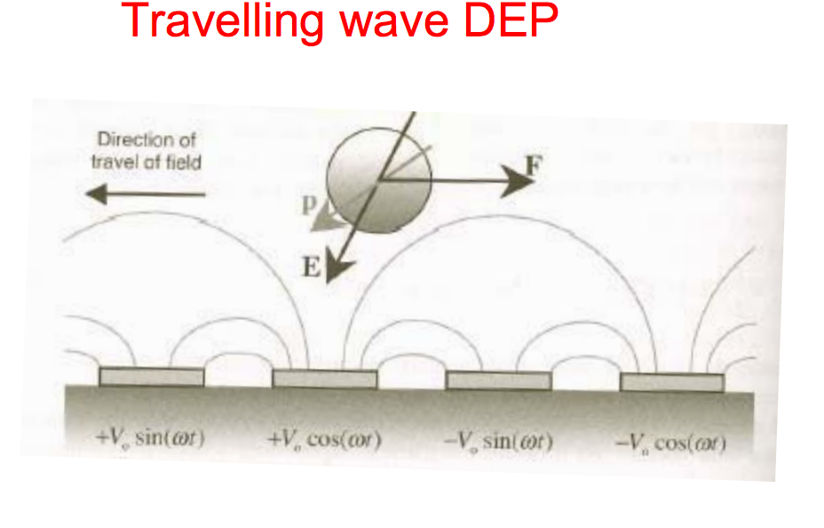
Magnitude and direction of Electric field gradient
The dependence on E2 indicates that the force direction is independent of the polarity of the applied field E and thus both DC and AC fields can be used. If the particle is surrounded by or immersed in a medium whose complex conductivity (or permittivity) is less than that of the particle, then the factor the resulting DEP force will be directed towards thehigh-field region. This is known as positive dielectrophoresis. See this paper[11] for details.
The magnitude and direction of the electric field gradient is heavily governed by the geometry of the electrodes and the voltage between the electrodes. For the simple case of two coplanar rectangular electrodes, for us to be able to move an object along X-axis the field gradient must be along the X-direction. Directionality of the field gradient is strongly coupled with the geometry of the electrodes. However, the key take away is that the dielectric moves up the gradient.
Scaling of forces with size of object and electrode
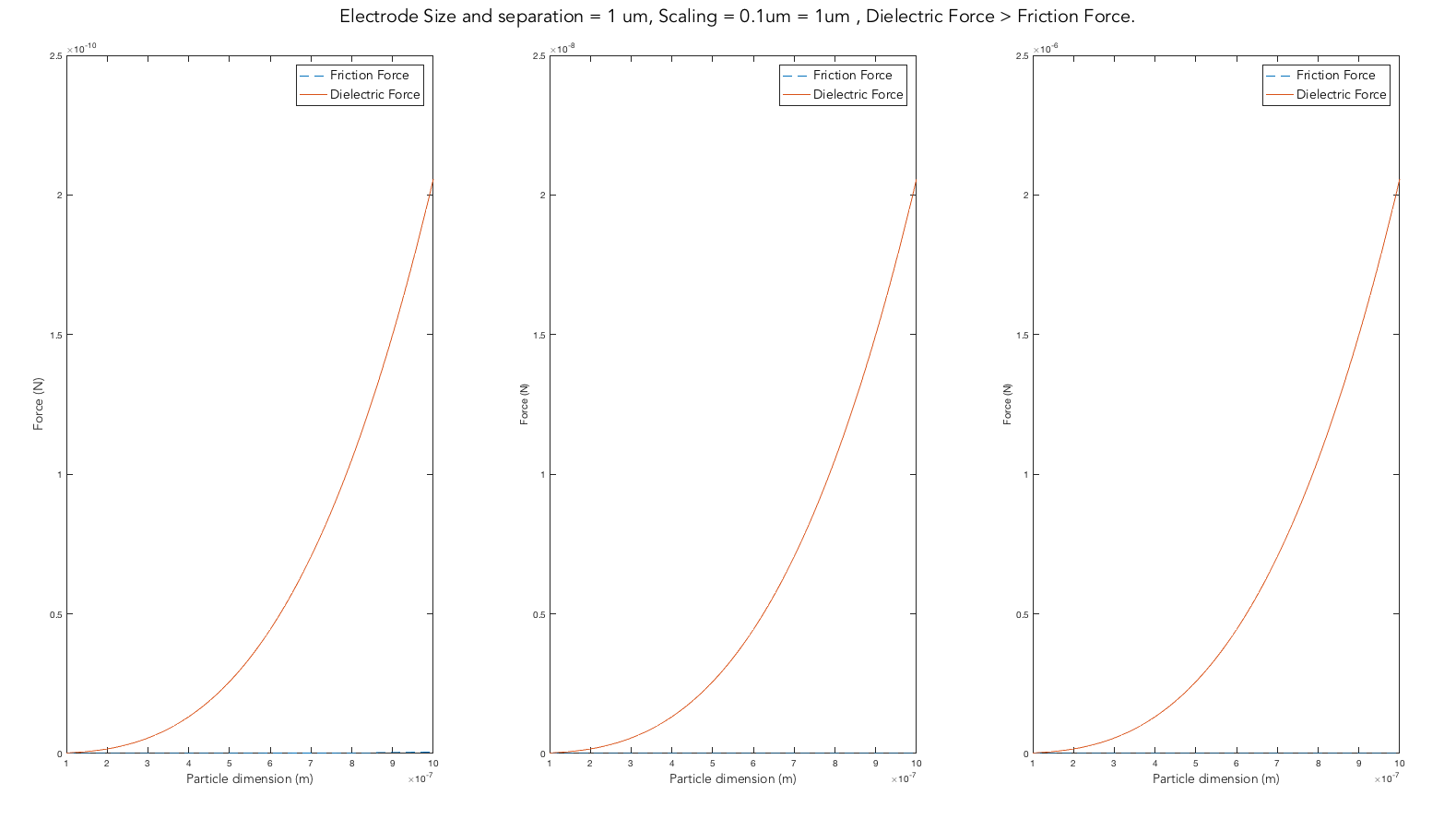
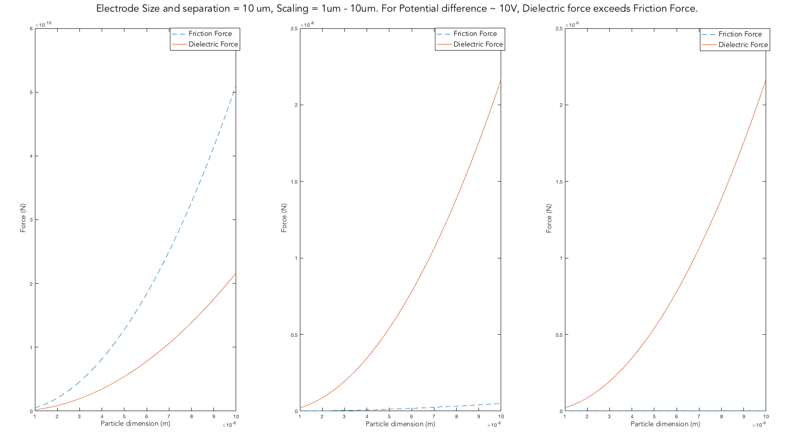
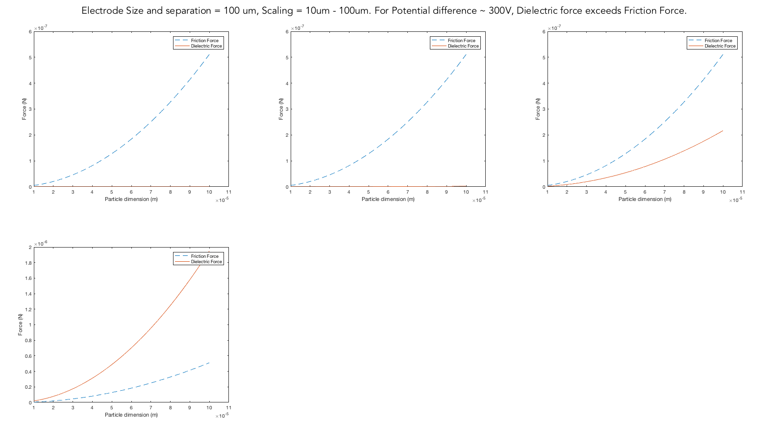
I looked at scaling of size of the objects at 3 sizes of electrodes, 1um, 10um and 100um. Following conditions hold good for all 3 cases:
- In each case, the gap between the electrodes and electrode size were the same.
- Object was scaled from 1/10th to the actual size of electrode.
- Scaling beyond the size of electrode needs better understanding of infuence of electrode geomtery on dielectric polraization and associated force.
Summarizing the plots
- For electrode size 1um, dielectric forces are much larger than the gravitaional force on the deielectric object. This is owing to the large fields and gradients dues to smaller gaps between electrodes.
- As the electrode size was increased to 10um, the applied voltage had to be pushed up to ~10V to generate enough dielectric force that competes with gravity.
- With 10 folds increase in size of electrode (100 micron), the potential difference between electrodes was required to be ramped all the way to 300V.
Clearly, as the size of the electrode and the object is scaled up, the potential has to be scaled up as well. The dielectric force scales more strongly with L, as F ∼ V2/L3. This means that in scaling from a system with L = 100 μm to one where L = 10 μm, one can reduce the voltage by ∼100× and get the same force. As further scale up to macroscale the voltage required grows to 1000V. One would need to apply 1000 V in the macroscale system to get the same force achievable with 1V in a microscale system.
As for scaling up the voltage, dielectric breakdown sets an upper bound on maximumn size of object that can be manipulated. Putting it differently, as the density (mass per unit volume) of the material increases, the size of the object that can be manipulated goes down.
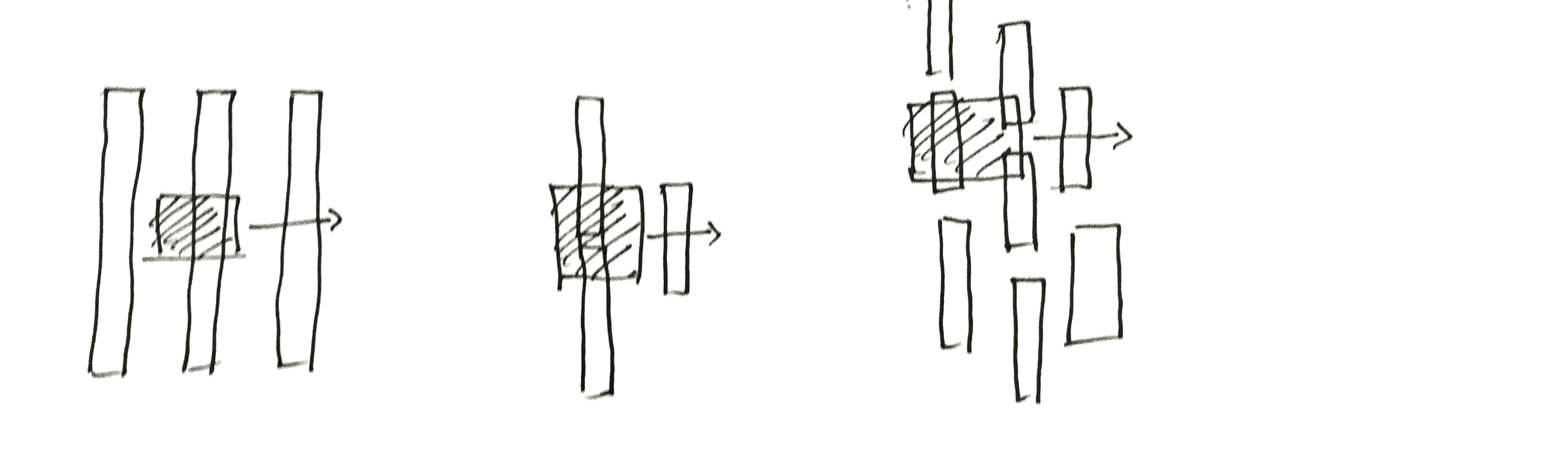
5. Geometry of electrodes and direction of force
A simple geometry consisiting of two electrodes of equal length gives no gradient in field ∇|E2| = 0.
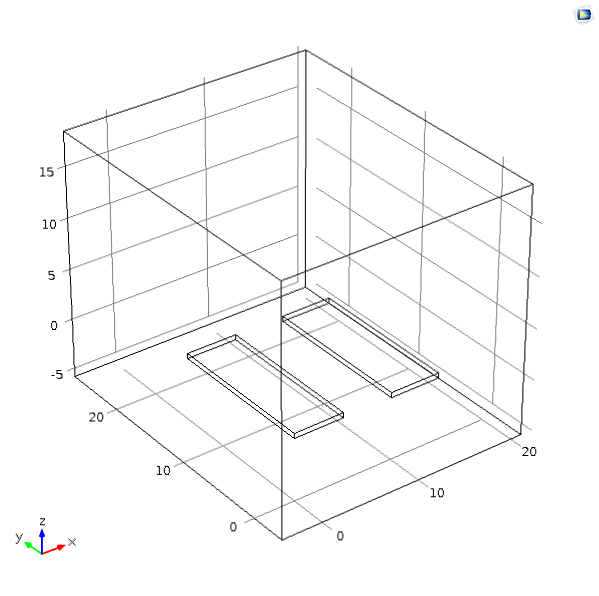
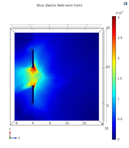
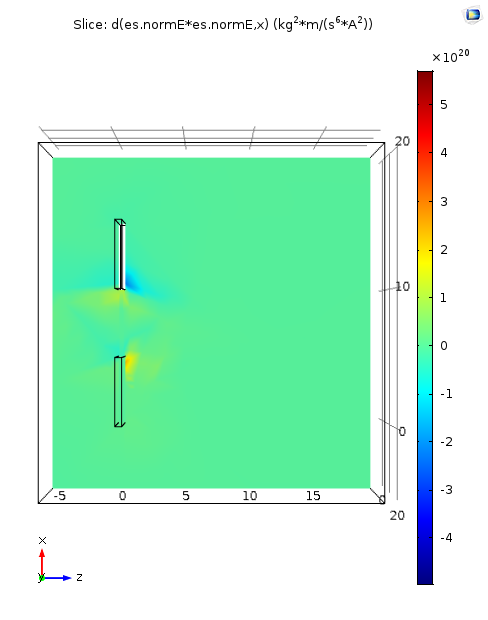
Uneven length in electrode gives gradient ∇|E2| >0 along x-direction.
6. Evaluation
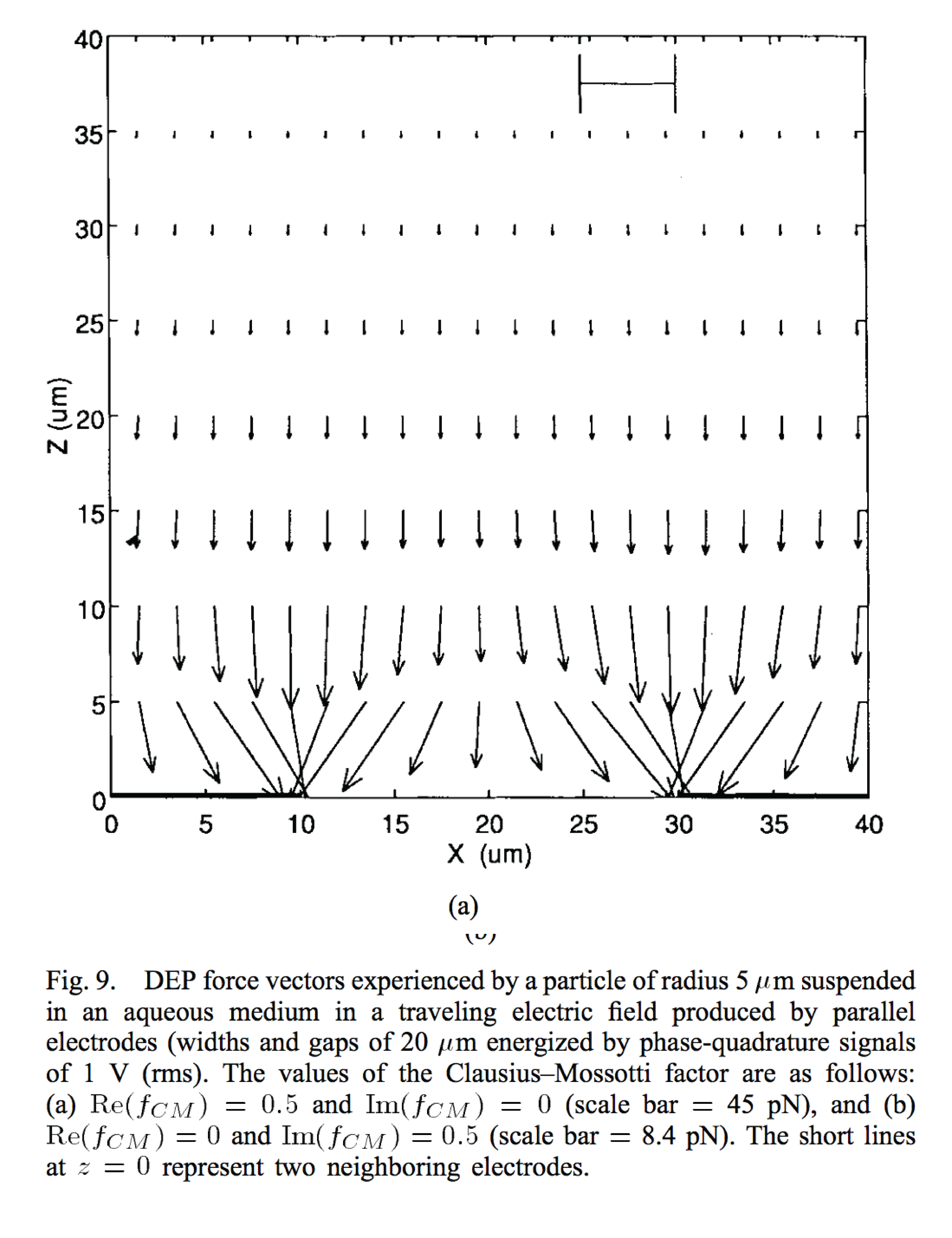
This paper talks about manipulation of particles suspended in an aqueous medium through dielectrophoretic force. Given below is a snippet of a plot of dielectrophoretic forces experienced by a particle of radius 5μm for an electrode of width and gap 20μm. At 1V between two electrodes of same size and particle size of simialr order, the results and analysis in this page are comparable with those in this plot.
- The dielectric force scales more strongly with L, as F ∼ V2/L3. This means that in scaling from a system with L = 100 μm to one where L = 10 μm, one can reduce the voltage by ∼100× and get the same force.
- As for scaling up the voltage, dielectric breakdown sets an upper bound on maximumn size of object that can be manipulated. Putting it differently, as the density (mass per unit volume) of the material increases, the size of the object that can be manipulated goes down.<
7. Future work
-
Figuring out a systemtic way for designing the geometry of planar electrode.
One possible way to design the electrode design procedure is based on the assumption that the electrical potential at any point (x,y,z) created by an electrode system of interest is defined by a polynomial that obeys Laplace’s equation. By substituting this polynomial into Laplace’s equation the corresponding equipotentials can be determined, and these in turn can be used to define the required electrode boundaries. Although the method can readily applied to three-dimensional systems, for the sake of planar manipulation we can restrict it to two dimensions.
- Exploit frequency dependence of relative dielectric permittivity to generate variable force.
References:
- Classical Electrodynamics by John David Jackson
- Introduction to Electrodynamics (4th Edition) by Griffith
- Classical Electrodynamics by Julian Schwinger (Author), Lester L. Deraad Jr. (Author), Kimball A. Milton (Author), Wu-yang Tsai
- Problems in Electrodynamics by V.V. Batygin, Igor N. Toptygin
- Electrohydrodynamics and dielectrophoresis in microsystems: scaling laws. A Castellanos, A Ramos, A Gonzalez, N G Green and H Morgan
- Ac electrokinetics: a review of forces in microelectrode structures. A Ramos, H Morgan, N G Green and A Castellanos.
- Basic Theory of Dielectrophoresis and Electrorotation. Thomas B Jones
- Effect of electrode geometry on dielectrophoretic separation of cells. Yoshikazu Wakizaka, Masaru Hakoda, Naohiro Shiragami
- Electrode design for negative dielectrophoresis. Y Huang and R Pethlg
- Dielectrophoretic Manipulation of Particles Xiao-Bo Wang, Member, IEEE, Ying Huang, Member, IEEE, Peter R. C. Gascoyne, and Frederick F. Becker
- Electrical Forces For Microscale Cell Manipulation. Joel Voldman.
Other Related Notes
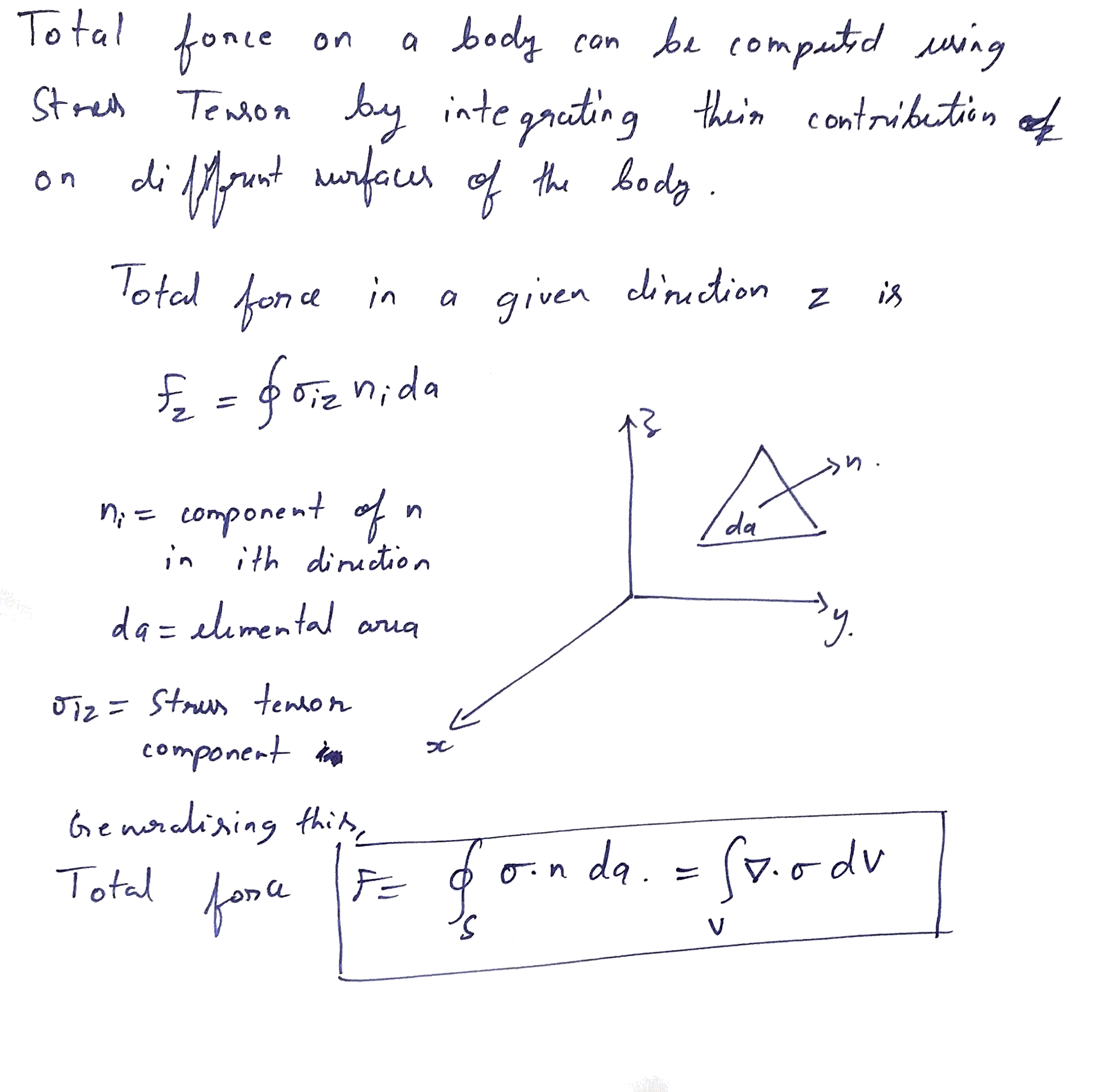
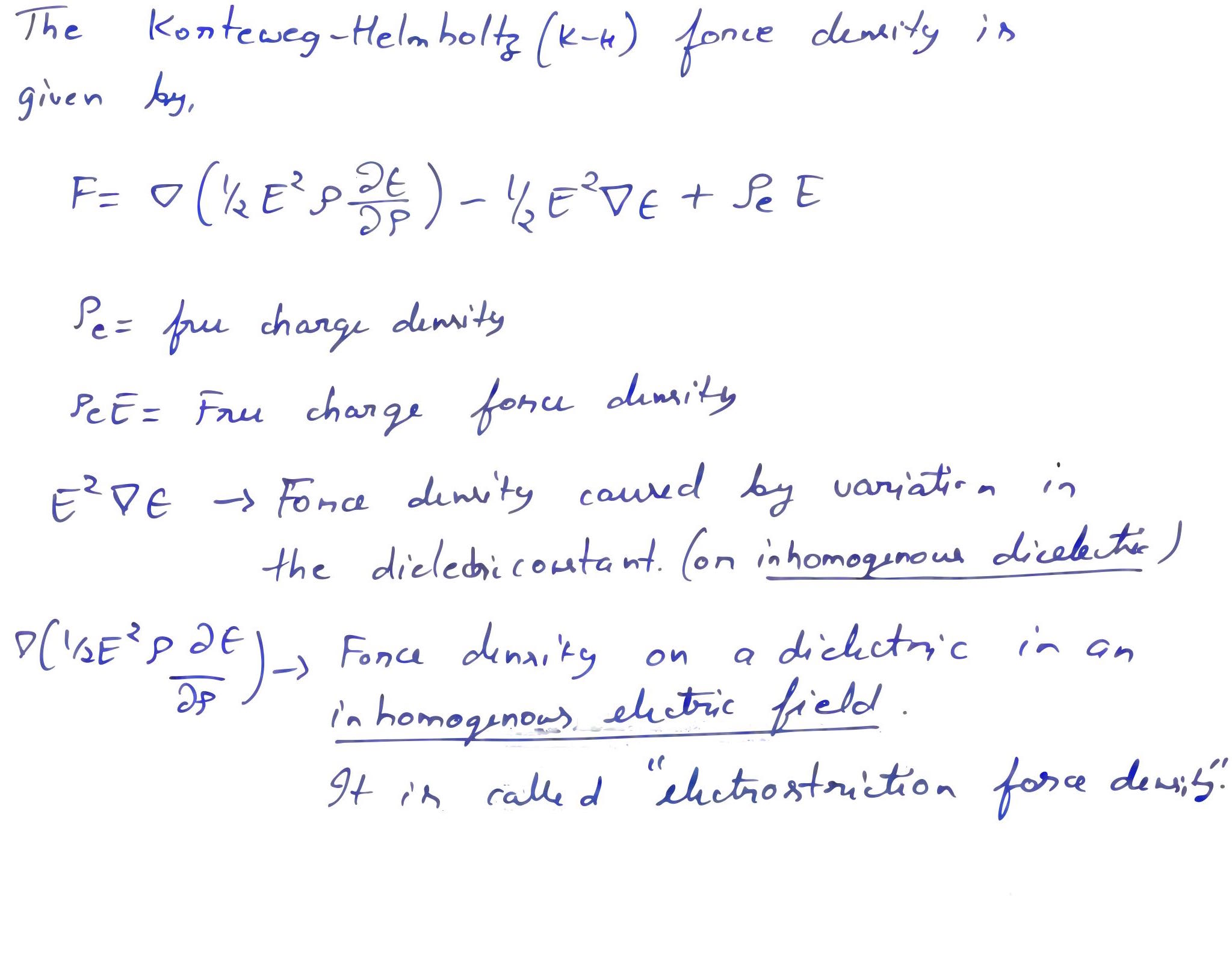
Maxwell Stress Tensor
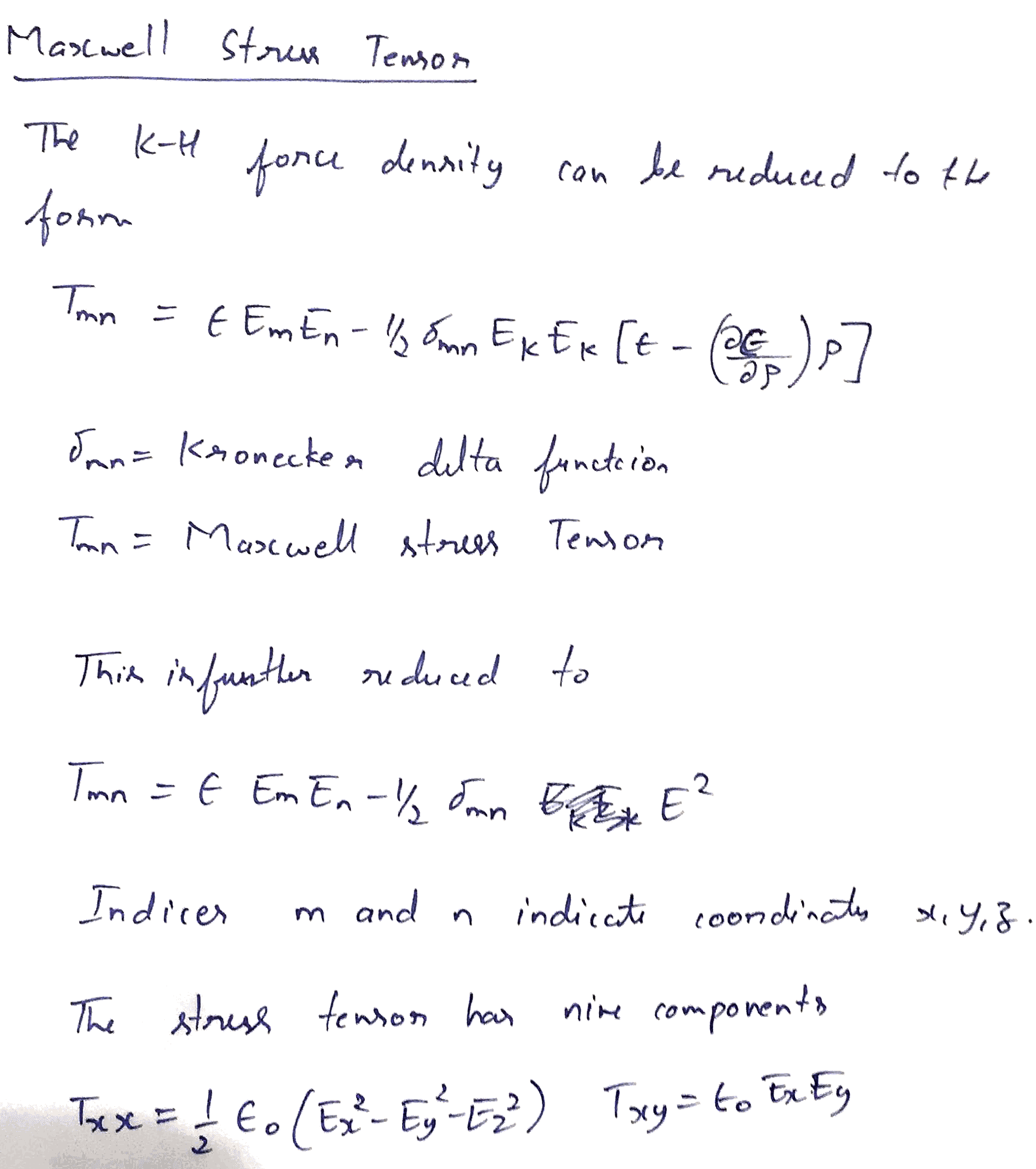
Total Force from Maxwell Stress Tensor