When you start Eagle the Control Panel should pop up.
Eagle Getting Started
This page provides a brief overview to getting started with Eagle the PCB Layout Editor. This page goes through a simple schematic layout for a high-pass filter in Eagle. It also contains instructions to layout the corresponding board in Eagle. In addition there are some tips for Eagle users and pointers to some additional resources. It also contains a link to information on the fab class (mas863) assignment for F'03 also with some additional resources.
Get
Eagle PCB Layout Editor (free version)
Let's build a simple high-pass filter!
Components (in libraries):
1 resistor
1 capacitor
1 ground
2 I/O ports
Steps
1) Start Eagle
|
|
When you start Eagle the Control Panel should pop up. |
2) Create New Schematic
|
|
To create a new schematic go to File -> New -> Schematic |
3) Add a resistor
|
|
Go to the Control Panel. Expand Libraries -> discrete.lbr -> RESUS-5. The library folders are organized by functionality and by manufacturer. Some symbols may be European and some may be US. RESUS-5 is the US symbol for a resistor. When RESUS-5 is selected two figures will appear. The figure on the left is how the resistor will look in the schematic view and the figure on the right is how the resistor will look on the board layout. When selecting a
component in a library you may notice one of two symbols next to the name of the
part. A parts symbol
|
|
|
Select ADD then left-click (on mouse) to place the part. Another window may pop up, just select Cancel. Press escape (Esc) to exit out of the mode. |
|
|
Set the name of the
resistor by choosing the Name button
|
|
|
To move the part
you can select the Move button
|
|
|
To rotate the part
you can select the Rotate button
|
4) Add a capacitor
|
|
Go to the Control Panel. Expand Libraries -> discrete.lbr -> CAP-5. |
|
|
Then add the capacitor and label it with 0.1uF as in step 3) |
5) Add Ground
|
|
Go to the Control Panel. Expand Libraries -> supply1.lbr -> GNDA. |
|
|
Then add the ground as in step 3) |
6) Add Input/Output ports
|
|
Go to the Control Panel. Expand Libraries -> solpad.lbr -> LSP11. |
|
|
Then add the I/Os as in step 3) |
7) Connect (wire) the components
|
|
Arrange the components using the move and rotate buttons. |
|
|
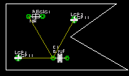
Here is a image before the circuit is connected |
|
|
To connect the
components use the Wire button
|
|
|
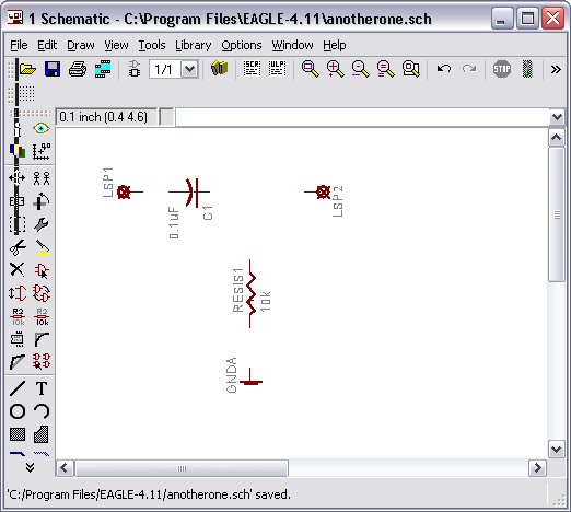
Here is an image of the circuit wired up in the schematic. |

Make sure to save your schematic. Now you are ready to layout the board!
8) Switch to board mode
|
|
To switch to board
mode you must select the Board button
|
|
|
A new window should pop up with your circuit on the left and a square on the right. The circuit will not look the exact same as the schematic, but it should be electrically equivalent. |
9) Place components on board
|
|
Arrange the circuit components on the board how ever you wish. This can be done by using the move button (in board mode) and selecting each component and dragging it to within the board boundaries. You can GROUP COMPONENTS too (see How do I... section below). |
10) Re-size board
|
|
Re-size the board by using the move button to move the (white) lines on the bounding box. Try to leave the left-most lines alone because they are aligned with the origin. Otherwise, you can shape the board any way you like (or of course you can just cut it out). |
|
|
The yellow lines are not actual connections they represent logical connections. |
10) Ratsnet
|
|
Select
the Ratsnest button |
11) Routing
|
|
Routing by hand: to route components by hand select the Route button
|
|
|
To remove a route select the Ripup button
|
|
|
Autoroute: to have the computer attempt to route for you select the
Auto button |
12) Design Rule Checking (Drc)
|
|
To setup the width, clearance, etc of your wires and components select the
Drc button |
12) Finished with board
|
|
Once you have finished routing your board then you can do a number of things. For example, printing (etching) your board with a Modela. |

Where
is/are…
Resistors and capacitors? discrete.lbr
Power and Ground? supply1.lbr
Input/Output ports (solder pads)? solpad.lbr
How do I...
Add a new library?
|
|
You can place the file.lbr in the lbr directory of Eagle. |
|
|
Or if you go to Options-> Directories put the cursor in libraries, and choose browse and locate the file folder with your fab library. now the library is in the control panel. you can have multiple locations for the libraries. |
|
|
Or when you are in schematic view, up top there is a library menu option. |
Delete?
|
|
To delete,
click on the (X-button) Delete button
|
Group Objects?
|
|
To group, Edit -> Group then create a window around the objects you wish to group. To move (or any other option) the group select the Move Button and right-click the group you wish to move. Then move it. |
Save an Image of my board?
|
|
In board mode go to File ->Export->Image. Then you can specify the resolution, the image file type, and where to save the file. |
Create a new part (and my own library)
|
|
File->New->Library |
Additional
Resources
Cadsoft
Eagle Tutorial & Manual
Modeling/Simulation Tools
 . A warning window might pop up
saying the board does not exist and then it will ask you to "Create from
schematic?". Select Yes.
. A warning window might pop up
saying the board does not exist and then it will ask you to "Create from
schematic?". Select Yes.  to set wires as shortest signal relation between two points. also tells you how
many connections have not been routed
to set wires as shortest signal relation between two points. also tells you how
many connections have not been routed  . Then follow the yellow line
connecting the components you wish to route together. The routing lines will
match Eagle's layer color.
. Then follow the yellow line
connecting the components you wish to route together. The routing lines will
match Eagle's layer color. and then select the line
segments you wish to remove. To remove all routes select the Ripup button then
select the GO button
and then select the line
segments you wish to remove. To remove all routes select the Ripup button then
select the GO button  .
. . Using the
menus you can set the costs to give bias to the layers, vias, etc.
. Using the
menus you can set the costs to give bias to the layers, vias, etc. . Browse through
the menus and change the settings to your preferences. Then once you select OK a
box called Drc Errors might pop-up showing you where all your design rules have
been violated on your board.
. Browse through
the menus and change the settings to your preferences. Then once you select OK a
box called Drc Errors might pop-up showing you where all your design rules have
been violated on your board.