this document assumes that you have laid out your circuitboard using eagle. it also applies to a single-layer circuit board only. it also doesn't use capitals.
In case all you want to do is make a PCB just follow the instructions. For everything else, I think you need to understand the MODELA brain (or guts if you think it has no brain).
First here is how an RML file ( the Modela language) looks like :
PA;PA;VS2;!VZ2;!MC1;!PZ-20,50;PU385,1240;PD367,1240;PD367,1229;!MC0;
The modela knows how to do 2 different things :
Move with the head up ( the command is PU ) to a given position x,y
Ex : PU385,1240; move with the head up to x=385mils y=1240 mils
Or move with the head down :
Ex : PD367,1240 moves with the head down to x=367mils y=1240 mils
How it works :
The command PZ-20,50 si defining what UP means and what DOWN means:
First values defines down as -20 mils from z=0 (z=0 should be the surface of the piece you want to cut).
Second values defines up as +50 mils from z=0.
So a PUx,y will move the head to x,y with the head at high z=+50 while a PDx1,y1 will move the head to x1,y1 with the head at high z=-20.
Providing you defined z=0 right :
With the head up (z>0) the modela is moving between points WITHOUT cutting.
With the head down (z<0) the modela is moving between points CUTTING
The last thing VERY important to know is how to define z=0 for the modela.
For this all you have to know is that each time you push the down or up orange button, the modela is resseting the z=0 to the current z position.
first off, note that the script you will be using assumes that you've put a 0-width trace on each layer outlining the board boundary. if you haven't, do that now.
once you have all your circuit layout up and wired, you need to export it as a gerber file. to do this, open File => CAM Processor. when then dialog box comes up, choose File => Open => Job.... this is where you choose the exporting settings. Pick gerb274x.cam. hit Process Section and you're done. a file with extension .cmp should be in the same directory as your board file. take this file with you to the modela pc.
there are several scripts you need to mill your board:
the white "view" button on the modela mill pauses any milling operation and puts the mill in view mode - pulling back the head and pushing the stock base forward for easy access. pressing it again will put the mill back in operational mode.
if necessary, change the mill bit to the one you need. for our purposes (and assuming you used a 15mil tolerance in eagle), a 10mil endmill should be good. this should be done in view mode.
you can easily change the endmill using the small hex key to your left.
a little lower.
yeah, this one.
the chuck of the modela mill has two holes. only one of them is a hex screw. the other is just a hole and you won't be able to turn anything around in it. if you have the wrong side facing you, you can simply rotate the chuck to get to the screw.
still in view mode, use double-sided tape to attach the copper plate to the milling base plate. then exit view mode.
this might seem trivial, but fastening is really important with the modela. several notes:
this is done using the move.rml script you have downloaded before. go to command shell mode (Run... => cmd in windows). change to the directory in which you saved the script file. then enter
type move.rml > com1
assuming the modela mill is attached to COM1 of course.
a similar method can be used on unix machines, enteringcat move.rml > /dev/ttyS0
the milling head has now moved to what might be a good starting position for your milling. if you need to adjust this position, open move.rml in a text editor, and change the values following the PU command (by default they are currently
PU1400,400. after saving the file send it to the com port again to see if you're closer to the desired mark.
finally, remember these x,y values. you will need them later on.
using the up and down arrow buttons bring the mill bit just a tiny distance over your stock. don't touch the stock with the mill, as it is spinning at this stage.
now, using the hex key again, release the bit, so that it just kinda drops onto your stock. tighten the bit in place.
for this we will use the cam.py script, which you downloaded from the link above.
run the python interpreter (in windows, open IDLE (Python GUI) in the program menu), and open cam.py.
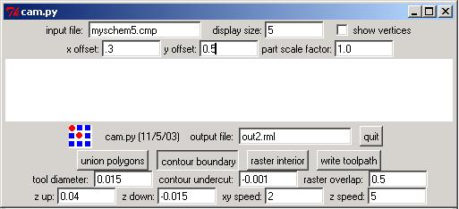
now run the script - Run => Run Module or f5. the dialog box below should open.
here you can load the gerber file (the one with the .cmp extention), and convert it to modela milling commands.
you can also use the command line interface to run python, in unix and windows. the simplest run would bepython cam.py or python cam.py yourboard.cmp. see
below for more command line options
input file field
this file should best be in the same folder as your python script.
display size changes the zoom you're viewing your circuit in. it has no effect on
the generated commands. note that the bigger the number, the further away you zoom your view.x offset and y offset correspond to the values you determined with the
move.rml script (see: above). The units here are in inches, whereas the units in move.rml
are in mils, so 1000 above means 1 here.part scale factor changest the scale factor of the actual part. you will probably
want to leave this at 1.0 (unless you can also scale your components, which you can't)output file name.tool diameter to match your endmill
(this field is in inches, too: 15mil = 0.015 )contour undercut parameter specifies how much undercut when generating the contour boundary. this amount is in inches and undercut for positive values and overcuts for negative. see section below on notes regarding this parameter
raster overlap specified how much overlap you have between neighboring raster lines.
0.95 means that there is only 5% overlap between neighboring mills. 0.5 would mean 50%.z down. for this task you will probably want to use -0.015. (inches again) z up determines how far to pull up between operations.x speed, y speed and z speed as is, unless you find out some particular feed needs. 2 is safe, i would say that even 3-4 is safe - and it saves raster time.
now you're ready to create the toolpaths. first run contour boundary - this might take a while. then add raster interior, and finally hit write toolpath to write the path to the rml file specified in the output file field.
when running python from the command line, you can pass several arguments. this will make your life easier, simply by not having to type them in every time.
cam.py is used as follows:
python cam.py [infile] [xoffset yoffset] [display size] [outfile] [undercut]
the undercut parameter tells the python script to undercut when generating the contour boundary. in other words, it offsets the tool placement by the specified number of inches closer to the trace than the toolsize
would normally allow.
this can be used to create a logically correct boundary, even when there is not enough clearance between the traces for the actual tool you're using. so, sometimes when you don't have enough clearance you can "cheat" the program in undercutting and correctly creating toolpaths between your lines. but note, that when milling, the tool may cut away from the traces and pads
you can also specify a negative amount (overcut) to make the traces wider than in your layout.
note: if you need too high or low a number to make your toolpath, the milling will almost certainly not succeed.
this is very similar to the usage of the move script. open a command shell, navigate to the directory of your output rml file (let's assume it's called out.rml), and then enter
type out.rml > com1
now make sure the mill is not in "view" mode, and the milling should start.
at some point you will probably want to not only stop a milling job (using "view") but to cancel it altogether.
in order to do that, you need to open your printer queue, and cancel the job there. under windows, you should have a little printer icon in your system tray (the area on the bottom right of your screen). double click on that, and right-click on your modela job (probably the only one there), then select "cancel". don't expect the job to disappear quite yet.
next, press the up and down buttons on the mill simultaneously and hold these down until the led starts to blink. it will take a while, but when the led stopped blinking, your job should have disappeared from the printing queue. you can now safely start a new job or put the mill back in non-view mode.
david lobosco wrote some useful tips for modela milling.