this can probably not be said enough: you will be software-driving a very
strong, very heavy, very fast tool that can easily kill people, including yourself,
and damage itself and other equipment around it. accordingly...
learn the location of the emergency stop
button blind.
do not do anything without the mill-door closed.
always wear safety glasses.
acquire the patience needed for dry runs and simulations.
finally, always keep in mind a picture
of yourself with a giant hole in your forehead.
this tutorial attempts to capture some of the information delivered in saul griffith's whirlwind address to the fab forum, and serve as an initial version of a tutorial for featurecam as a operation-generating software for the haas mini-mill. since it is (at this stage) based on word-of-mouth rather than direct experience, much of this information might be missing/wrong. This tutorial sincerely hopes to be updated in the future based on more unmediated knowledge, but should be a good skeleton for doing so.
the images are scaled for easier reading of the documents. click to see a full-resolution version of the screenshot.
featurecam is developed by engineering geometry systems which offers a trial version on their site. It is currently installed on the pc in the waterjet room, as well as on a pc in room E15-023. rumours have it that there is an installation on nemo, but I haven't been able to find it there.
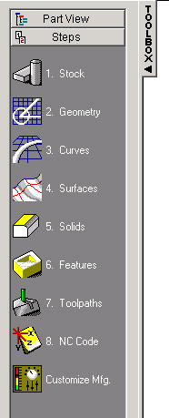
featurecam operates in a step-by-step approach creating your milling operations. as you progress through the various steps, operations are created that can be edited on every level even after they are complete. the steps in the toolbar on the left of the user interface are a good guideline to follow when making your milling operations.
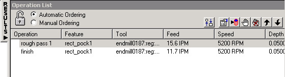
on the right of the user interface you can see the current results of your decisions. this is a list of sequential milling operations, each of which has a tool associated with it and a long list of additions parameters, such as the geometry and the feature it is milling. double-clicking on any result allows you to back-edit any property of this milling operation.
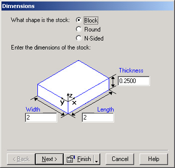
step one of everythins is naturally choosing the dimensions and material of your stock. to do
this, click 1. Stock.
featurecam continues to be joyfully step-by-step-ful, guiding you through setting the dimensions and the material using easy to understand dialogs. you can choose one of the many predefined materials or set your own if you know its unit horsepower and hardness.
you usually want to design your parts in an external program, such as coreldraw, and then
import the design into the featurecam. the program itself has a limited geometry editor, that can
be used for simple things (such as rectangles, fillets and circles), but is not convenient
to use for more complex drawings. the recommended import format is version 14 dxf .
when you import something into featurecam, it will create a default stock size. you can go back to change that in the stock step.
also, note that importing dxf might give you a warning. this is usually ok and shouldn't alarm you.
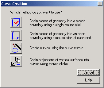
you can skip step 2 if you imported your geometry. 3. Curves is needed anyway. this
turns your geometry into curves. most importantly, it connects curves to turn them into single
tool operations. you do this by choosing the first option in the curves dialog, "Chain
pieces of geometry into a closed boundary"
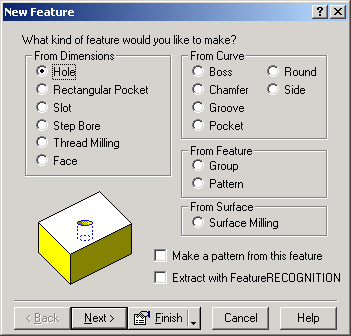
this is arguably the most important step, since here you actually create a milling operation
("feature"). this is under 6. Features.
there are way too many options to go through them all, but as the main dialog implies
you can create a feature either by setting the dimensions manually (i.e. specifying locations
and dimensions of holes, pockets, slots etc) or by operating on curves (which you created in the
previous step). curve features include bosses, chamfers, pockets, sides etc.
depending on what feature you choose to mill, you will get different dialogs to set the feature-specific settings. these are usually step-by-step and supported by straightforward graphical explanations.
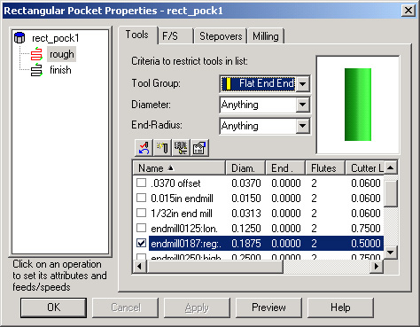
featurecam lets you choose the tools, feed speed and rpms for your milling tools. unless you know better, you should generally follow the program's recommendations for feed and speed. the tools you should choose manually, according to the tools that you actually have. if you want finer work, you usually up the rpm and lower the feed speed.
for most milling operations you want to do a rough operation first and then a finish operation.
a very important part of choosing your tool is specifying which tool number it is, since
the GCODE generated for the haas will automatically select a tool based on this number,
and it's much better for your
mental and physical health if the tool your code uses is actually the physical tool that
you believe to be in the cradle.
for example, you do not want featurecam to specify tool nr.1 thinking it is a nice little
.25'' endmill, when in case tool nr.1 in the haas is a 5-inch nuclear saw.
to set up the tool number when you look at the tool, you want to go to tool
manager, and under "current crib" - choose HAAS. the tool number is then set under
"default tool registers".
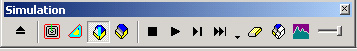
when you're all done, you can simulate the toolpath on your stock. you usually want to do
a 3d simulation. you can do that by choosing View => Simulations => Start => 3d Simulation
from the menu. there is also a little simulation tool window to choose your simulation type
and start a simulation.
one of the nicer features of featurecam is that you can back-edit operations after you're done. by double-clicking on any operation, you can edit the tools, tool number, feed and speeds, and every other aspect of the feature that generated this operation.
in the top of the tree on the left of this dialog is the feature that generated these operations. choosing that allows you to change the feature settings (curves, locations, dimensions etc). choosing any of the milling operations under this features allows you to change specific milling operations.
in addition, at any time, you can go back to any of the steps and change your stock, curves or geometry.
your final step is generating your nc code for the mill. this is pretty simple, but you need a license for that. get a floppy disk, and when prompted, save your GCODE as a text file on that disk.
to change the view on your part, right-click the part view and choose a different view. "Isometric" is the 3d view (as opposed to "Top" or "Side").