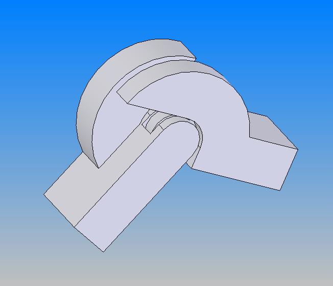
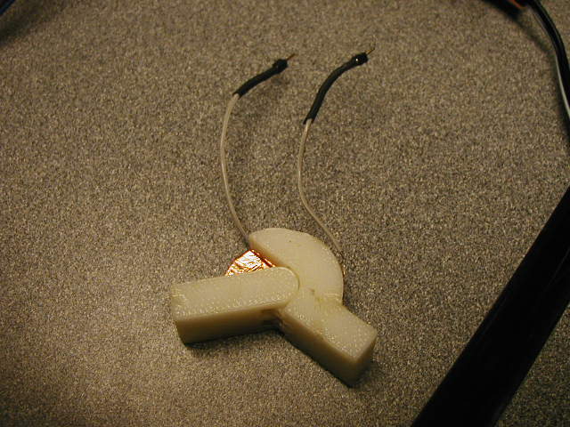
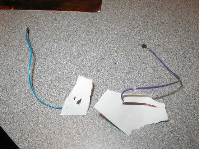
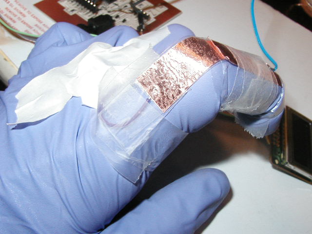
First, I wanted to make a trial run through capacitive sensing. One part of this was to make a joint with a capacitive sensor. To do this, I used the 3d printer to make the joint and tried to use the vinyl cutter to make sensors for the flat parts shown below. Unfortunately, this did not work well, but cutting the copper by hand with a knife worked great.
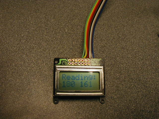
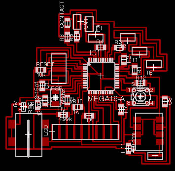
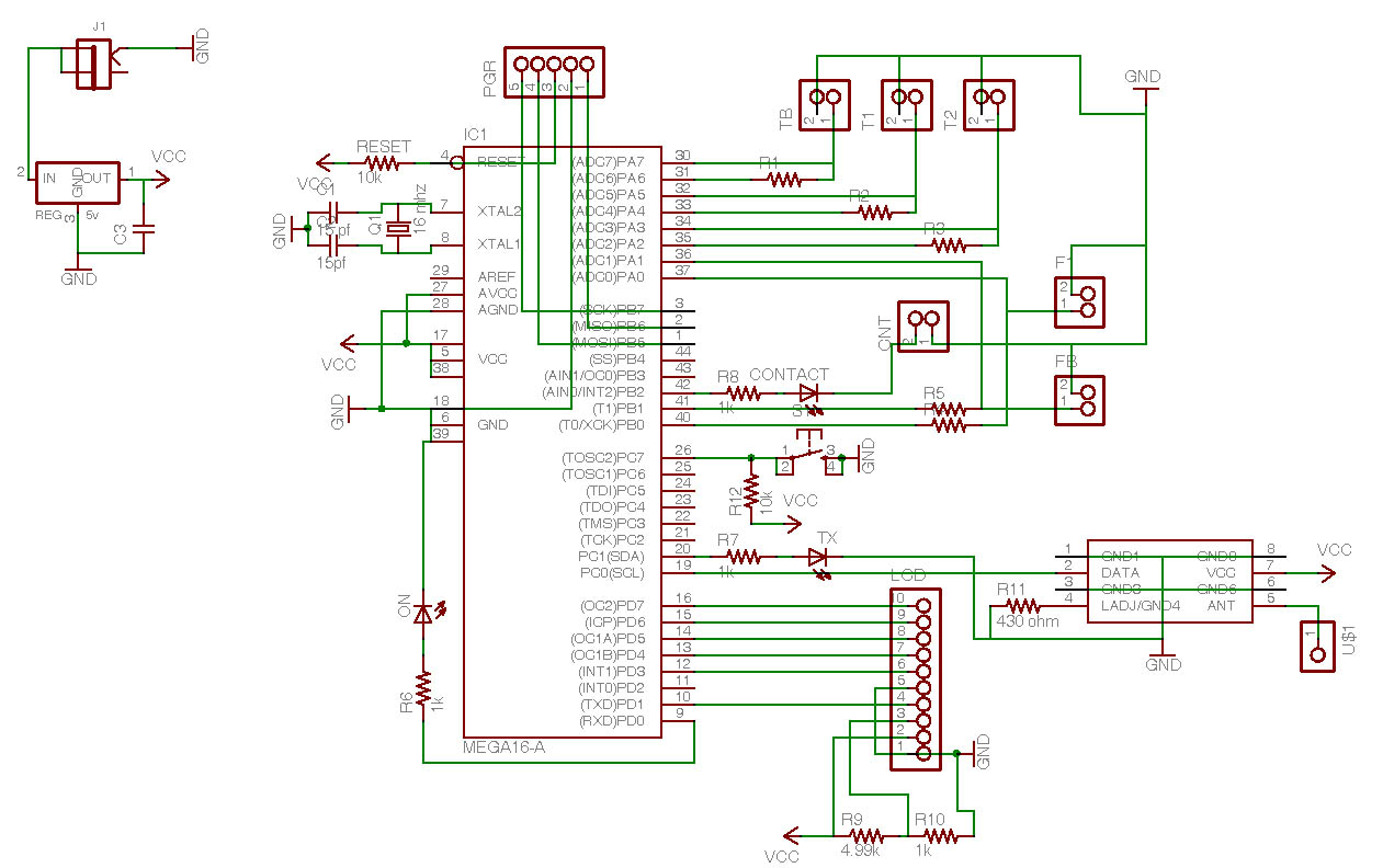
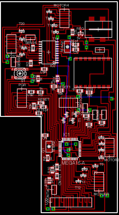
I also needed a board which could read a capacitive sensor and send information to an LCD display. In doing this, I also made the board capable of external clocking, motor control, and led-blinking.
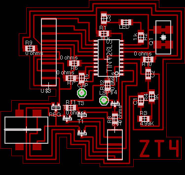
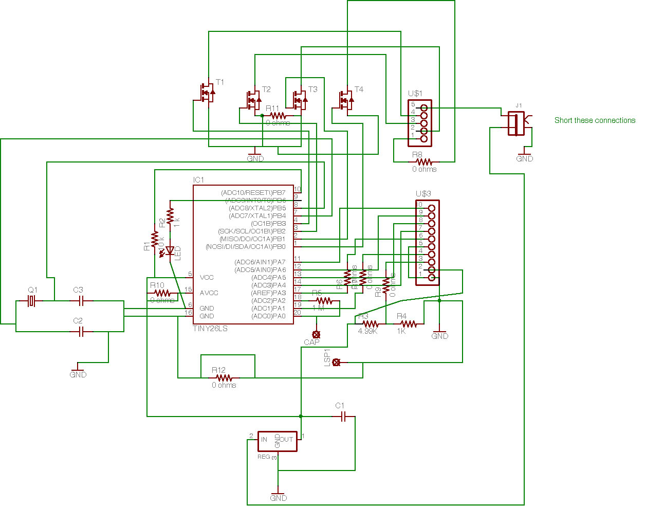
To program the microcontroller, I had to get comfortable using C on the attiny26. The code below does the following:
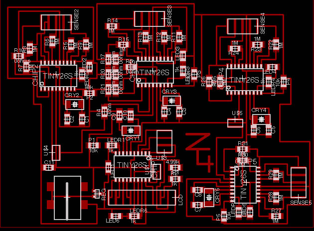
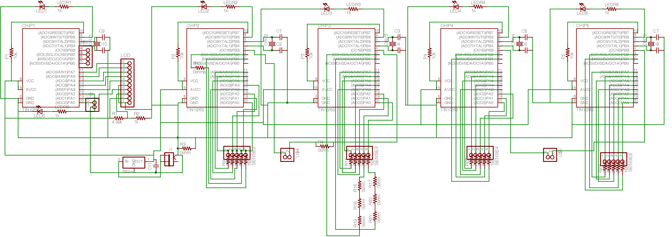
Finally, I designed the board which will be used on the glove sensor. It has 5 externally clocked attiny26's which blink LEDs. 4 of the boards take readings from capacitive sensors. The 5th compiles these reading and sends them out over a line. The 5th board can also control an LCD for debugging.
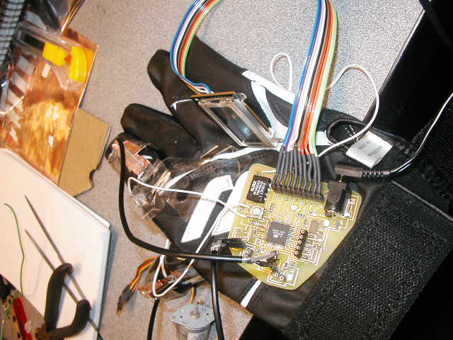
In the final stages of this project, I decided to simplify it. The result was a two board system where the first board read five values from a glove fitted with capacitive sensors. The other board would be attached to a mechanical hand which would also use capacitive sensors in a feedback loop to judge position. The glove would then send signals to the hand wirelessly. The two boards are shown here:
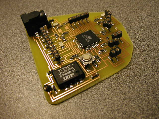
The final boards are shown here (glove, top; hand, bottom):

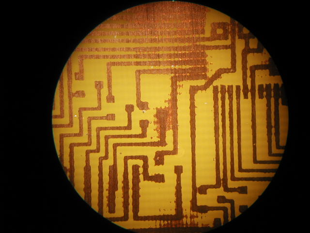
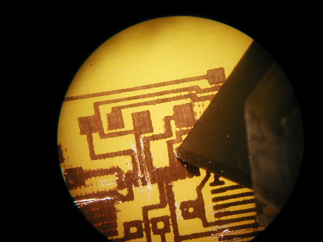
The first board I etched, the glove board (left), came out well. However, the second board came out very unclear. It is shown here under the microscope. I had to cut the traces apart by hand with a knife.
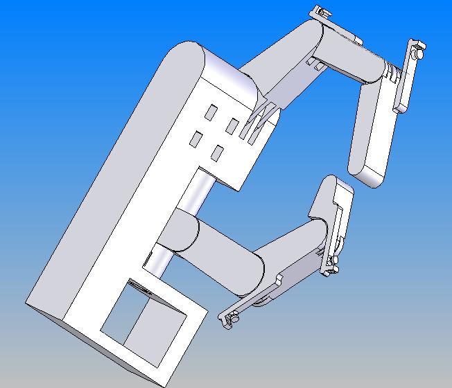
My initial design for the hand was an SBS plastic hand made on the Stratasys. However, I felt guilty using the machine for the required 40 hours, so this design did not get made.
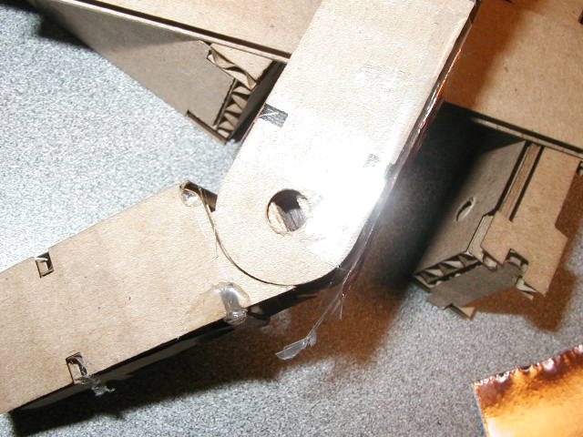
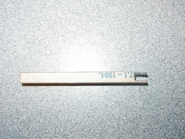
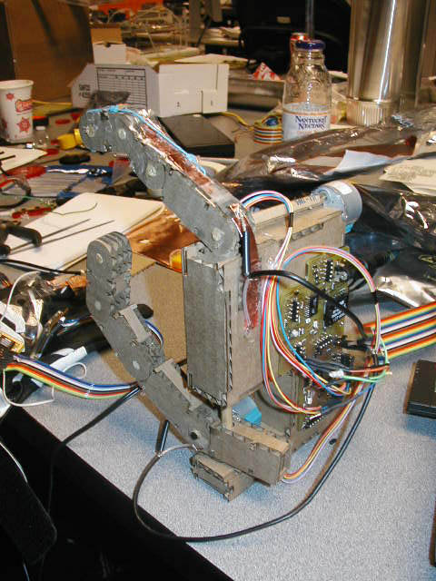
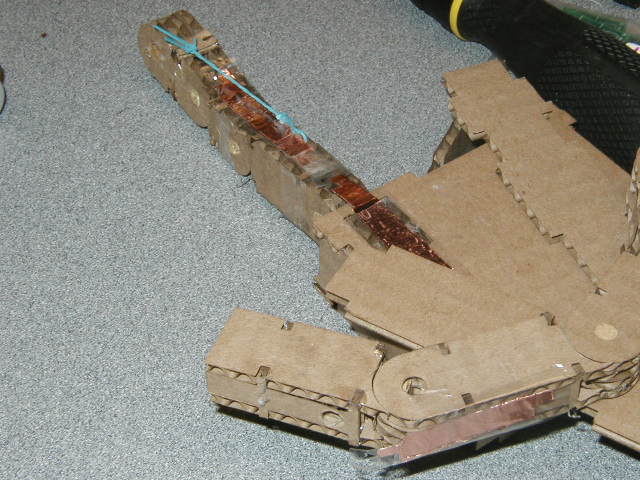
Instead, I designed a press-fit cardboard robotic hand. Pieces of wooden dowel were added at the joints to strengthen them.
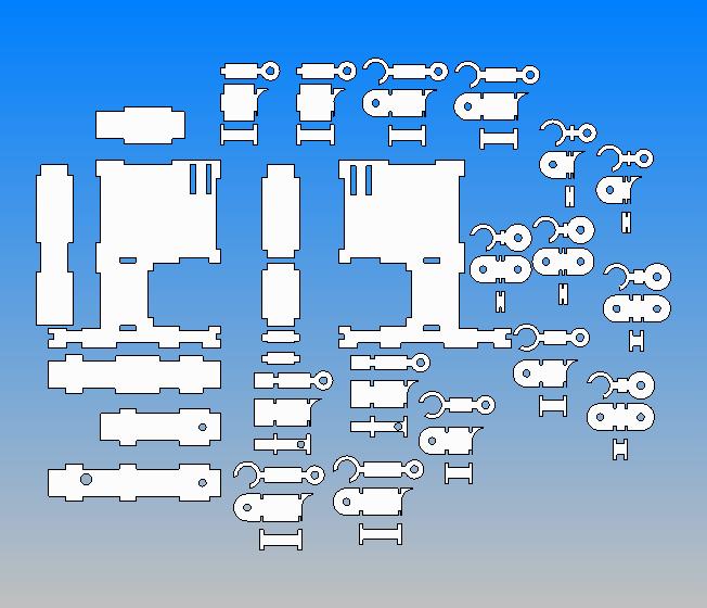
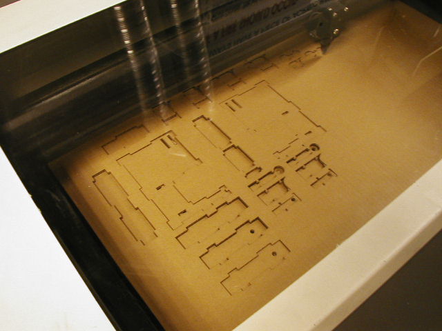
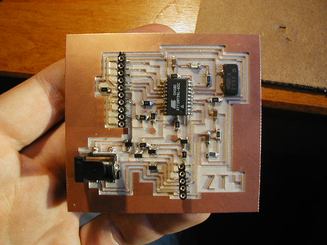
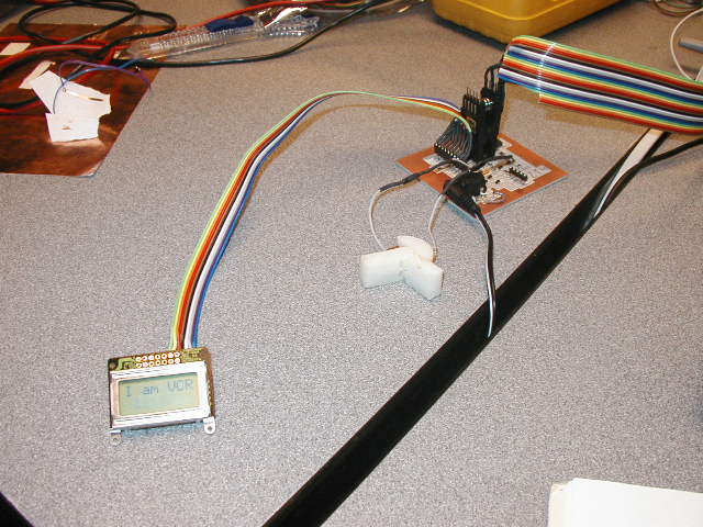
The first sensing glove was a disposable lab glove. Using the capacitive sensing capabilities on the early monster board, shown here, I wrote C code to measure capacitance and display an associated value on an LCD screen. Unfortunately, I could not get this code to work on the ATMega32. The sensors were cut using laser-cut wood pieces as patterns.
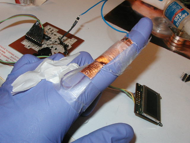

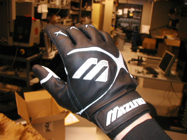
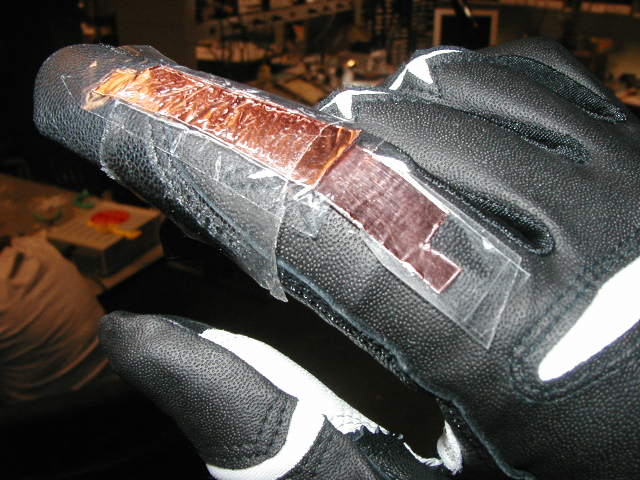
The final glove was a baseball batting glove which fit very well. One capacitive sensor was added to the thumb to measure the bend of the extreme joint. Another sensor measured the penultimate joint of the first finger, and a third sensor measured contact between the first finger and the thumb.
To attach the motors to the hand, I cut out the core of one of the dowels for one motor and made a shaft out of acrylic on the vinyl cutter for the other.