final project: For my final project I intend to build an injection
-molded pony that can be controlled either by sound or by using a handheld
IR controller.
For the IR controller details see details on my week9 page. For the
rest of the circuitry I have developed a 5 tiny13 design. One tiny13s
for each of 2 surface mount microphones (as yet these have not arrived from
digikey). One for each stepper motor, of which there will be two, one
to provide forward/reverse motion and one to steer. The last of the
tiny13s will be used to output light via LEDs and sound via a PWM speaker.
In part this last microprocessor is intended to abet trouble-shooting
of the circuit as I build it.
My first attempt to build this circuit was an largely unmitigated failure.
The nmosfet contacts for one of the stepper moters were reversed and
as a result it wouldn't function. I had trouble programming the chips
as well. My next attempt yielded much better results. I also changed
my strategy in building the board, testing each tiny13 subcircuit independently
and adding more LEDs for diagnostics. I managed to get both stepper
motors running, all the LEDs operating and all the boards communicating
with one another. Unfortunately, one chip in particular proved impossible
to reprogram so I couldn't get the board to function entirely as I
wanted, but as a proof of concept I am quite satisfied with this
preliminary result.
At present, using capacitve switches instead of microphones to guide
the device it functions as follows. Touching the "left" turn button
starts both the turning and the driving stepper motor. The left turn
LED blinks as well. Touching the "right" turn switch casues both
steppers to run as well. Touching both leave only the driving motor
running. Unfortunately, and for reasons that remain obscure to me,
the tiny13 that takes output from the switches and passes it to the
steppers will not respond to programming so I can't modify the drive
stepper to change direction or in fact turn back one the switch has
either been released or a second pin touched. This potentially the
most troubling detail as it will be imperative that I am able to readily
reprogram future iterations of the board. A picture and some files
below.
Note the actual board is a bit of a kludge.
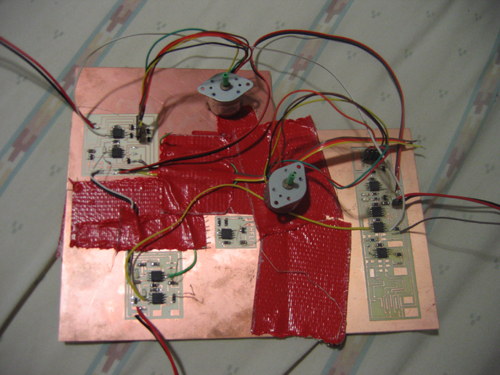 Hoping that this might help, I scratched out the transmit and receive
leads connected to the turning stepper/LED control board. It worked!
I am now able to program the board and reconnect the circuit using
off-circuit wires. As yet I have two capcitive switches controlling
two stepper moters, a driving motor and a turning motor. When the left
turn switch is touched the driving motor turns smoothly and the turning
motors twists roughy 40 degrees to the left. The same sort of thing
happens when the right switch is touched. When both are touched the
stepper turns back from the direction it was last turned and the driving
motor turns. So, as yet, I can go forward, left and right using two
switches. I would like to go in reverse as well and add an external
control, ideally IR. I'm having a bit of trouble with the IR range
though so I'll simply connect the controller and the vehicle by wire
to begin. If i can boost the IR range I'll cut the wire. Also I added
two LEDs, one that blinks when the left switch is touched and one that
blinks when the right switch is touched. When both switches are touched
both LEDs blink.
-> .sch of final circuit
-> .brd of final circuit
-> .cmp of final circuit
-> .asm of chip 1
-> .asm of chip 2
-> .asm of chip 3
-> .asm of chip 4
-> .asm of chip 5
I managed to send and recieve clicks via IR LED and via sound. Given
that I have yet to figure out how to send binary via either of those
transmit schemes my final boards will be flexible to allow for either
to be implemented as the last minute. The latest, and I hope final,
.brd, .sch and .cmp files are below.
-> .sch of final circuit
-> .brd of final circuit
-> .cmp of final circuit
-> .sch of controller
-> .brd of contoller
-> .cmp of controller
This afternoon I milled what I hope to be the final boards for this
project, one for a controller, one for the actual controlled vehicle.
Having as yet not decided between IR and Sonic com I've designed the
board to accomodate either.
Hoping that this might help, I scratched out the transmit and receive
leads connected to the turning stepper/LED control board. It worked!
I am now able to program the board and reconnect the circuit using
off-circuit wires. As yet I have two capcitive switches controlling
two stepper moters, a driving motor and a turning motor. When the left
turn switch is touched the driving motor turns smoothly and the turning
motors twists roughy 40 degrees to the left. The same sort of thing
happens when the right switch is touched. When both are touched the
stepper turns back from the direction it was last turned and the driving
motor turns. So, as yet, I can go forward, left and right using two
switches. I would like to go in reverse as well and add an external
control, ideally IR. I'm having a bit of trouble with the IR range
though so I'll simply connect the controller and the vehicle by wire
to begin. If i can boost the IR range I'll cut the wire. Also I added
two LEDs, one that blinks when the left switch is touched and one that
blinks when the right switch is touched. When both switches are touched
both LEDs blink.
-> .sch of final circuit
-> .brd of final circuit
-> .cmp of final circuit
-> .asm of chip 1
-> .asm of chip 2
-> .asm of chip 3
-> .asm of chip 4
-> .asm of chip 5
I managed to send and recieve clicks via IR LED and via sound. Given
that I have yet to figure out how to send binary via either of those
transmit schemes my final boards will be flexible to allow for either
to be implemented as the last minute. The latest, and I hope final,
.brd, .sch and .cmp files are below.
-> .sch of final circuit
-> .brd of final circuit
-> .cmp of final circuit
-> .sch of controller
-> .brd of contoller
-> .cmp of controller
This afternoon I milled what I hope to be the final boards for this
project, one for a controller, one for the actual controlled vehicle.
Having as yet not decided between IR and Sonic com I've designed the
board to accomodate either.

 -> .sch of ir led module
-> .brd of ir led module
-> .cmp of ir led module
Binary over IR is up and running! .ASM files for test boards are here.
-> .asm for i06 board
-> .asm for i07 board
With the IR reliably tranmitting/receiving I am now integrating the
rest of the project's functionality. I've changed the plan a bit so as
to use the two steppers opposed to one another on the back of the pony/car.
A Left turn command will send a single step pulse to both moters with
the same polarity. Similarly for a right Turn. Forward and Reverse
will work by driving the steppers in opposite directions. Prior to
assemling the housing for the project everything works as desired,
IR trans and motor control. Time being short I'm going to laser cut a
housing for the devices instead of injection molding something. The
.sxd of the remote and control housing appears below.
-> OODraw .sxd file of final projet
The assembly of the IR remote went smoothly and the device functioned
without any problems when sending binary encoded IR to the test i07
board I had connected serially to my computer. Assembly of the car
was more problematic as there were a few details I hadn't thought fully
through, specifically, the placement of the stepper motors. Eventually
I did get the car assembled and was happy to discover everything working
as it ought to. Sadly, the steppers blew out in succesion and I was
left with a quickly modified my little pony turntable. Fortunately
I had added vis LEDS so I could verify that there was IR com to the pony
and the lone surviving stepper shakes in such as way is to indicate
that it is receiving com, but fails ultimately to spin or step as desired.
-> .sch of ir led module
-> .brd of ir led module
-> .cmp of ir led module
Binary over IR is up and running! .ASM files for test boards are here.
-> .asm for i06 board
-> .asm for i07 board
With the IR reliably tranmitting/receiving I am now integrating the
rest of the project's functionality. I've changed the plan a bit so as
to use the two steppers opposed to one another on the back of the pony/car.
A Left turn command will send a single step pulse to both moters with
the same polarity. Similarly for a right Turn. Forward and Reverse
will work by driving the steppers in opposite directions. Prior to
assemling the housing for the project everything works as desired,
IR trans and motor control. Time being short I'm going to laser cut a
housing for the devices instead of injection molding something. The
.sxd of the remote and control housing appears below.
-> OODraw .sxd file of final projet
The assembly of the IR remote went smoothly and the device functioned
without any problems when sending binary encoded IR to the test i07
board I had connected serially to my computer. Assembly of the car
was more problematic as there were a few details I hadn't thought fully
through, specifically, the placement of the stepper motors. Eventually
I did get the car assembled and was happy to discover everything working
as it ought to. Sadly, the steppers blew out in succesion and I was
left with a quickly modified my little pony turntable. Fortunately
I had added vis LEDS so I could verify that there was IR com to the pony
and the lone surviving stepper shakes in such as way is to indicate
that it is receiving com, but fails ultimately to spin or step as desired.


