assignment: To modify the circuit board and assembly code from last
week so that the board could send and receive data and blink an LED.
details: This project, despite its apparent simplicity was much more
difficult as it entailed learning much of the software that was
transparent to us last week.
Beginning with Eagle, I had a lot of difficulty making the connections
in the .brd file. Ultimately I realized that this was because the grid scale
was set too high by an order of mag and as a result the program would not
snap to the desired pin connections. Once I had resolved this issue
completing the .brd file was simple. For the actual layout I synthesized
the .sch files from two other boards that were posted on the class site,
one that blinked while sending data in the fashion of the first board
and another that was designed to receive and send back an incremented
character. Links to the .sch, .brd and .cmp files are included at the
bottom of this page. An image of the completed board appears below.
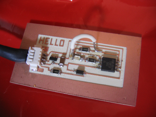 Of note, my original routing of the circuit was incorrect. To correct
the board I used tweezers to scratch out one of the milled connections
and used a wire to jumper the correct circuit.
Revising the assembly code was also fairly straightforward. I simply
cribbed code from the two boards described above. One difficulty I had,
and that led to hours of fruitless troubleshooting, was that I had
misidentified one of the board pins and as a result the LED was not
operating as I had expected. Once I corrected the assembly code the
LED began to operate correctly. One additional modification I made to
the assembly code was to reverse the order of the sbi and cbi commands,
resulting in short blinks with long pauses rather than long blinks
interupted by short pauses. Links to the .asm and .hex files used in this
project appear at the bottom of the page.
A screen caputer of the python interface is shown below, demonstrating
the incrementation of the input character.
Of note, my original routing of the circuit was incorrect. To correct
the board I used tweezers to scratch out one of the milled connections
and used a wire to jumper the correct circuit.
Revising the assembly code was also fairly straightforward. I simply
cribbed code from the two boards described above. One difficulty I had,
and that led to hours of fruitless troubleshooting, was that I had
misidentified one of the board pins and as a result the LED was not
operating as I had expected. Once I corrected the assembly code the
LED began to operate correctly. One additional modification I made to
the assembly code was to reverse the order of the sbi and cbi commands,
resulting in short blinks with long pauses rather than long blinks
interupted by short pauses. Links to the .asm and .hex files used in this
project appear at the bottom of the page.
A screen caputer of the python interface is shown below, demonstrating
the incrementation of the input character.
 -> .sch of new board
-> .brd of new board
-> .cmp of new board
-> .asm of new board
-> .hex of new board
-> .sch of new board
-> .brd of new board
-> .cmp of new board
-> .asm of new board
-> .hex of new board