| row# | force | #cuts | result |
|---|---|---|---|
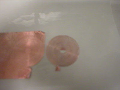
| 1 | 48 | 2 | PERFECT, one shot weeding, allows for very fine spirals |
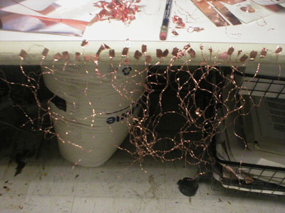
| 2 | 48 | 2 | result too connected to use |
| 3 | 49 | 2 | result too connected to use |
| 4 | 49 | 2 | result too connected to use |
| 5 | 49&50 | 3 | result too connected to use |
| 6 | 51&52 | 2 | result too connected to use |
| 7 | 55 | 1 | too heavy, tears copper |
| 8 | 54 | 2 | decently weedable |
| 9 | 54 | 2 | weedable, but a bit tricky. |