Video
It turns out that the video signal a TV uses is possible to recreate with a tiny13 and a few resistors. The signal varies between 0 and 1 volts, where 0.3-1 volts represents black to white, and 0 volts is used as a synchronization signal (diagram).
In order for the tiny to output a number of voltages between 0 and 1, I constructed a network of resistors. Each pin can be +5, Gnd, or Tri-Stated (disconnected), which leads to a number of possible output voltages (3^4 possible states with by using 4 pins). In order to determine the resistor values that would give me the best spread of possible voltages over the 0 to 1 volt range, I wrote a program that for a given set of resistors graphically displays all possible voltage values that can be achieved through different pin states, assuming a 75 ohm impedance for the TV (Green squares represent 0, 0.3, and 1 volt - red dots represent the values that can be acheived):
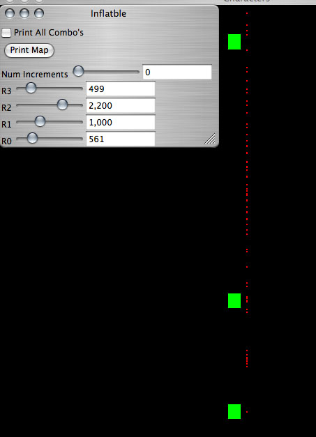
This program also can print, for each desired voltage, the closest attainable voltage and the pin states required to achieve it. I used this data to build a map from desired volatages to pin states in the tiny13.
As an example of what the chip could do I set it up to output a solid gray square to the screen, and to take information in via serial to set the brightness of the square.
A badly shot movie of my typing commands over serial and slowly increasing the brightness: tv_serial.mov or tv_serial.mpg
Serial input was difficult, since the lenth of a byte at 38400 baud (the fastest I was able to get to work reliably) is significant longer than one scan line on the television. This means that the serial reading must be interlaced with the video signal generation. I wrote a small function which is designed to be called at a constant rate (faster than the bitrate of the serial connection) that polls the input serial pin and keeps track of its values. When a full byte is received in this manner, the function stores that byte and resets itself to begin receiving again. This way, the video generation and serial input can be interlaced by repeatedly switching back and forth between polling the serial pin and setting the video signal level.
jgtv9.asm - Assembly File
jgtv8.sch - Schematic
jgtv8.brd - Board Layout
ResistorLadder.java - Resistor calculator - won't work without my codebase, but has the resistor math.
edit