| 13oct2005 - Third Assignment |
There are two main aspects to a bicycle driven water pump - the pump itself, and the interface to the bicycle. A main reason why I am interested in *bicycle* driven pumps, in particular, is the ability to utilize the inertial momentum of a spinning bicycle wheel.
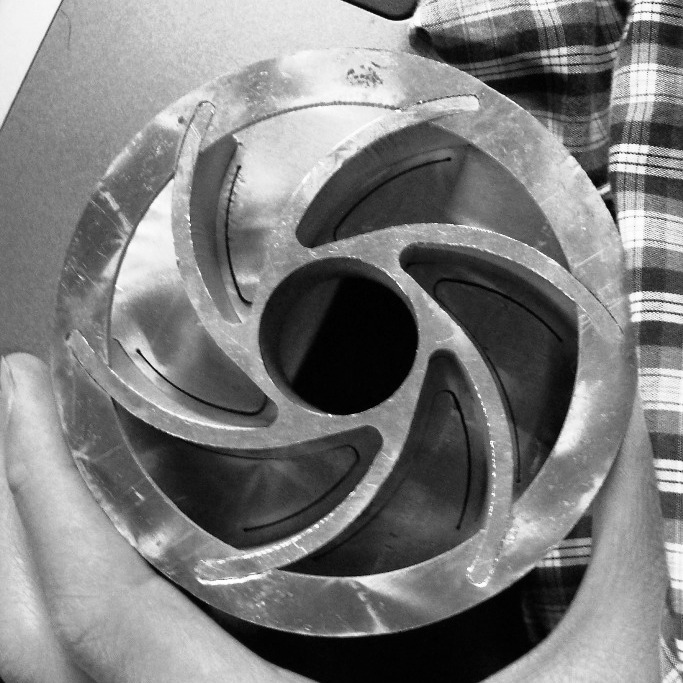
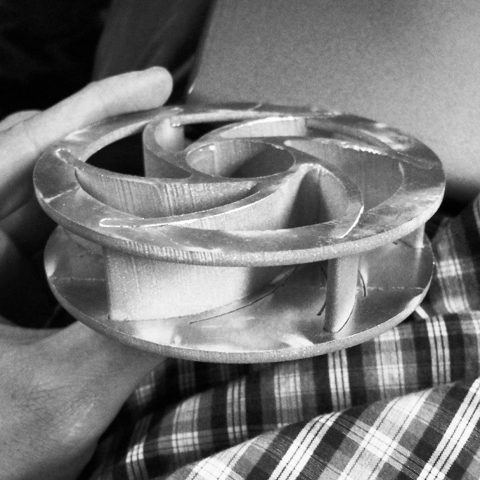
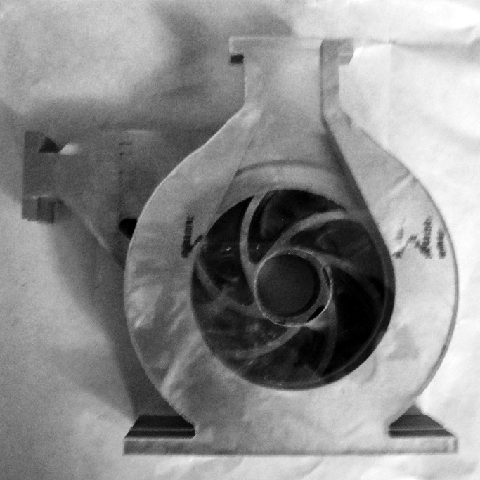
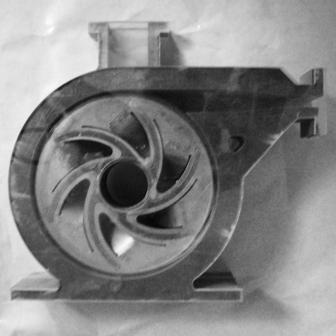
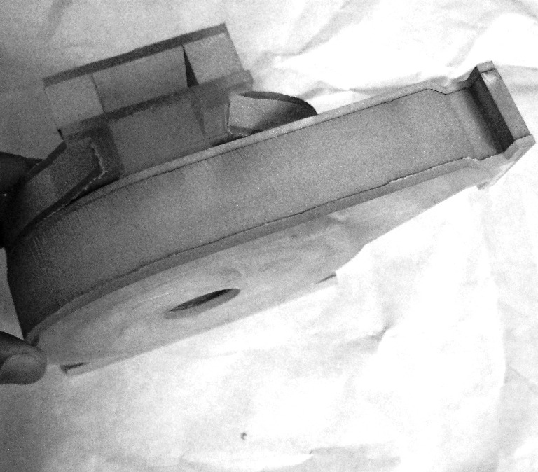
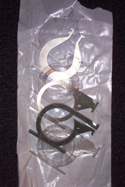
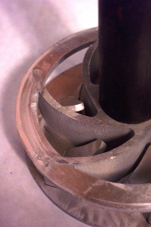
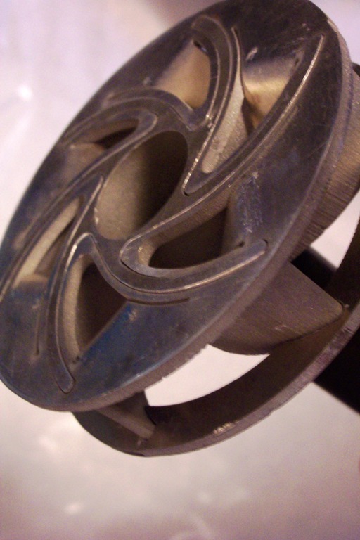
As for the design of the pump, there are a number of different kinds of water pumps that are conventionally used. It seems that the best choice for this application is a centrifugal pump with a fan-like impeller. Fundamentally, most types of combustion engines that produce torsional output may be reversed for use as a pump (with torsional input). However, piston style pumps do not lend themselves to rapid design and fabrication, for operation at high speed, and similar tuning would be required for something that operated like a wankel (rotary) engine in reverse. I opted for something similar to small turbines, but adapted to press fit and two dimensional fabrication methods (i.e. the water jet).
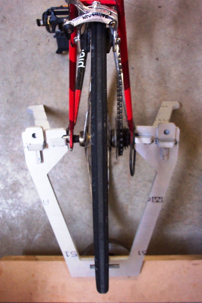
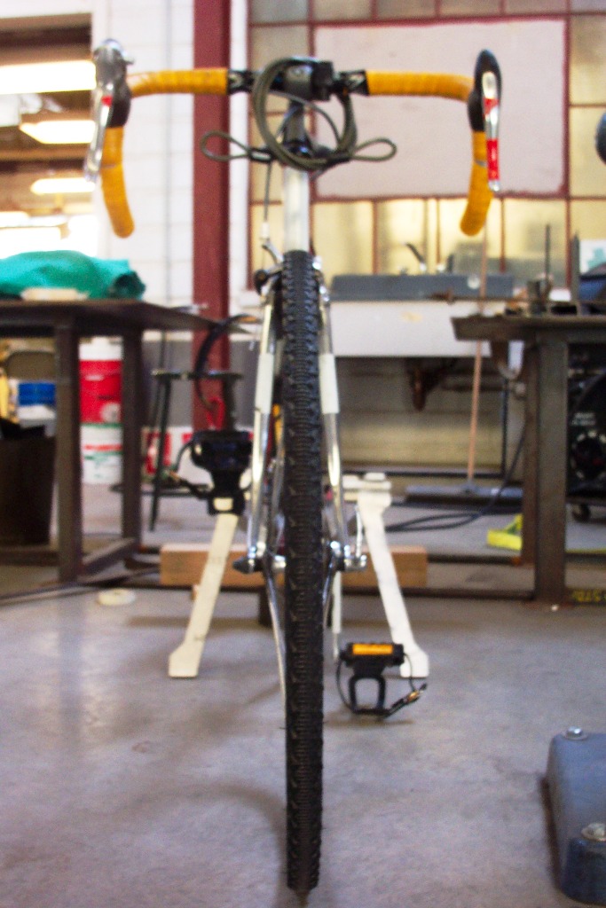
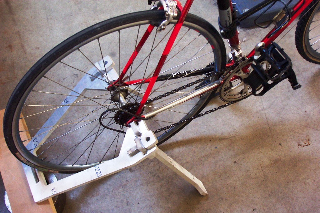
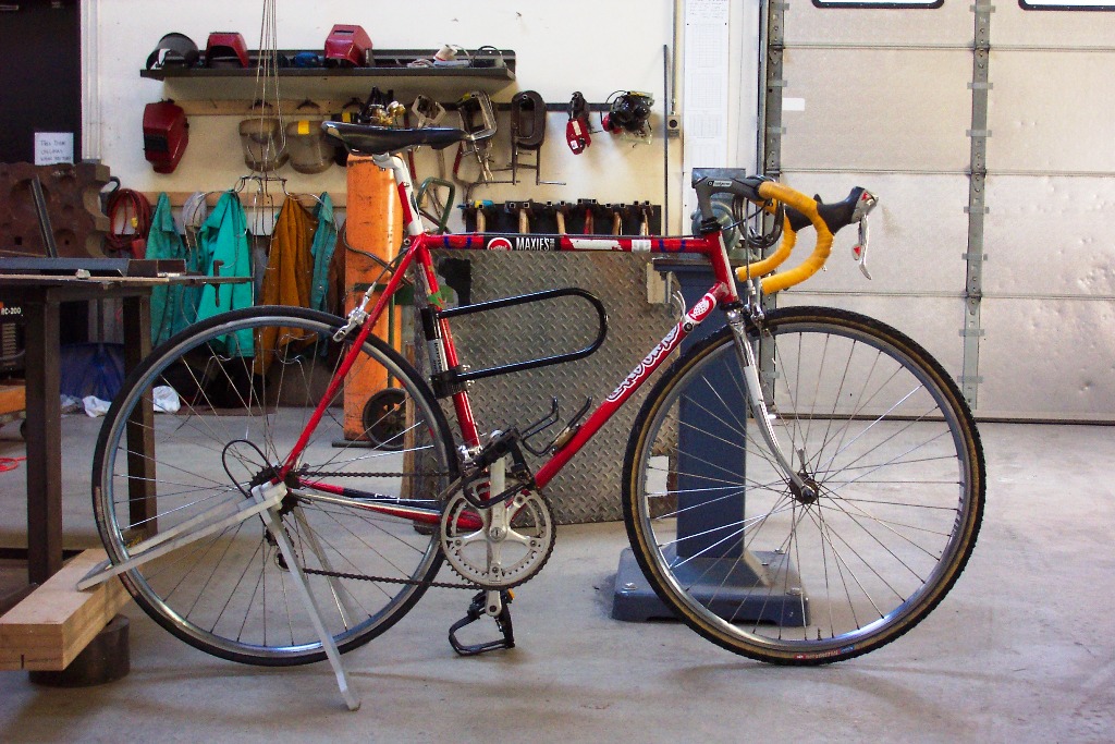
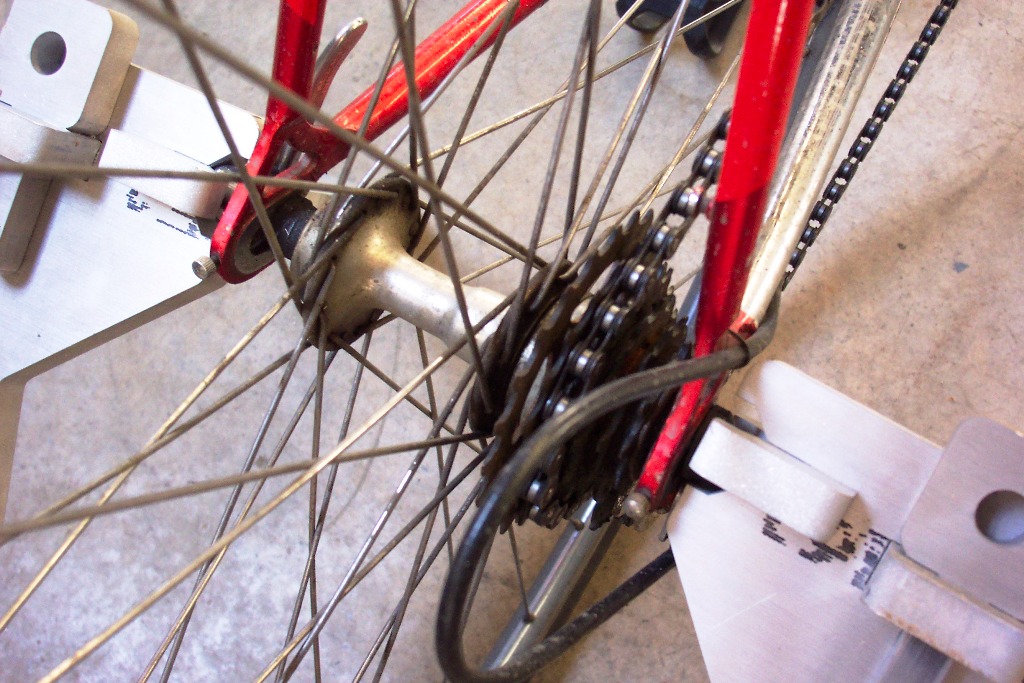
As for the interface to the bicycle, there seems to be two transmission options - using the friction of the tire (and corresponding rotational speed ratio resulting from using different diameter input and output shafts), or directly driving the pump with a chain (probably less sensible). Regardless of how the transmission occurs, there needs to be a method for holding the bicycle in a stationary position, with the rear tire off of the ground. So, I designed and fabricated an aluminum stand that is meant to attach over the rear axle of the bicycle, very much like conventional trainers. The pieces press fit together, with 0.001 inch tolerances. When I first tried to fit the pieces together, they immediately siezed and caused what appeared to be blistering of the aluminum. With high pressure lithium grease, however, the pieces all fit together snugly, with the help of tapping with a hammer.
One quick note... the bicycle used to test, shown in the pictures, is not the bicycle that this stand is designed for. It is designed for a 130mm hub spacing (common on all but the newest racing equipment) and 26-inch diameter rims (also quite common), with <2" tires. The hub and gearing setup shown does match this, but all I had around were 700c road rims, so it appears that the wheel is a bit large. The next iteration will acommodate all wheel standards (including recently revived 29ers, perhaps).

|
| 06oct2005 - Third Assignment |
While making a lighting device with the laser cutter was a bit of a stretch (although hyperbolic surfaces would make for interesting fixtures), I've been interested the design of bicycle driven water pumps, and it seems that the water jet cutter would be a good application.
Materials used... steel, aluminum, and a bicycle. All parts press-fit together.
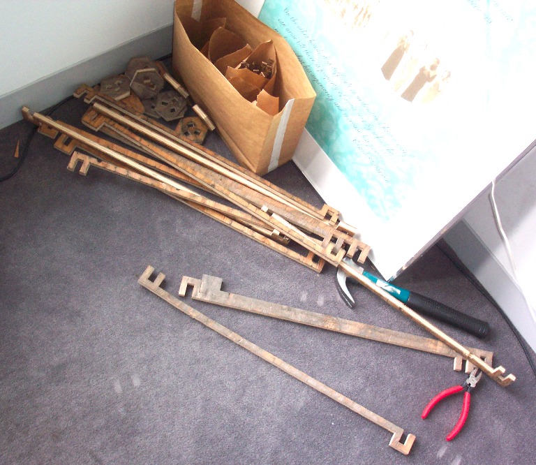
As something of an aside, I did try to make a big version of my invention kit, out of plywood, using the water jet cutter. Fundamentally, a scaled up version of my invention kit would be quite useful for inhabitable structures. At the very least, one could make tent-like structures; at most, one could develop a versatile, structural basis for high density, three dimensional city infrastructure. Okay, maybe a bit of a dream, but in the absence of Malthusian population checks, something about our cities needs to change, otherwise we may carpet the earth with something like suburbia. Anyway, there are a number of existing (mostly suburban) geodesic structures that rely on similar principles, in a way that does not make use of its extensibility and versatility.
Unfortunately, the dynamics of the plywood that I used, when the invention kit pattern was simply scaled up, do not correspond to those of the cardboard. The relative strength of the joint areas and connector lengths do not compare to those of the cardboard. Despite a dramatic increase in the slenderness of the connector pieces, the torsional rigidity of the wooden connector lengths is greater than the breaking strength of the wooden joints with the nodes, resulting in breakage of the wooden connector pieces, close to the nodes. It seems that I got fairly lucky with the connection design of the cardboard invention kit, and a change in scale and materials may require significant redesign of the connections.
|