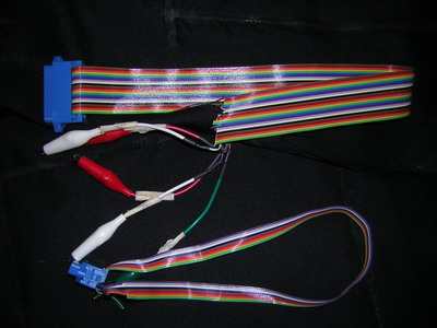
figure 1
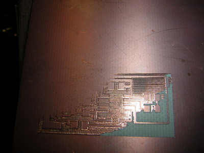
figure 2
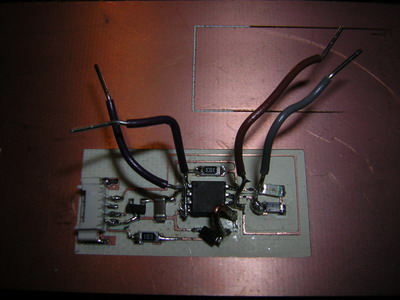
figure 3
WEEK 5
This week's assignment was to make parallel and serial cables for programming and communicating (figure 1) with a modified chip of the one we made last week. This chip added the ability to receive data over the serial connection as well as control an LED.
My first issue was working with the Modela. The first time I tried to make it print the board, the cuts were not deep enough (set at .005 in the z down direction). With John's advice, I changed the z down direction to .007. This only solved half of the problem as the cut was only deep enough for half of the board (figure 2). I then decided to move the schematic over three inches to the right. At this position, the Modela cut the entire board out very well. No one seem to know what could have caused this problem, but I would recommend that people go ahead and start on the right most side of the board.
The next problem was
with programming the chip. After many failures at this, I built a
second programming cable with alligator leads rather than the clip.
Unfortunately, while I was putting leads on the Tiny13 I pulled up some
copper and broke the connection. So far I haven't gotten it to work,
but I will keep trying.