Stacy DeRuiter's How To Make Almost Anything Blog - Week Seven
How to Measure Almost Anything - Digital Volt Meter
Monday, October 31, 2005
This week, the class will be working on a cooperative assignment - each of us will start designing and building a chunk (one sensor, component, or interface) of an "How to Measure Almost Anything" device. Tom and I are assigned to make a digital volt meter (dvm).
Wednesday, November 2, 2005
We decided that we wanted to make a dvm that can measure DC voltages from 0-15V (the max we think a computer might send out to a hello world chip), and that will use the hello world board's Vcc (about 5V) as its reference voltage.
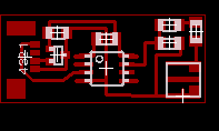
We succeeded in laying out a schematic of the PCB we would like to use for our dvm and routing it.
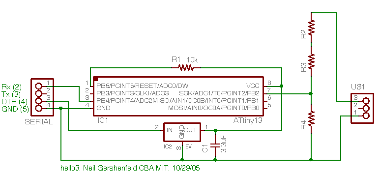
Want the actual eagle files the pictures came from for some reason? Here they are:
dvm.sch
dvm.brd
We basically decided to have a probe input pass through several resistors in series...the resistors serve to limit current (that's why we chose to use relatively large 1k resistors - that way the input should be well below the 40mA that the pins on the tiny13 can handle) and also to step down the input voltage. Because we have 3 resistors in series and we send the input to the tiny13 ADC pin between the second and third resistors, the input voltage to the tiny should be 1/3 that of the original input. (Therefore, a 15V input will not exceed Vcc, the reference voltage -- so it will be measure-able, and will not fry the board either.)
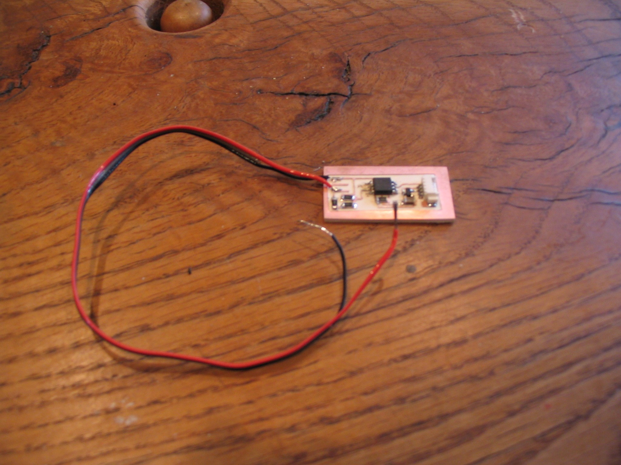
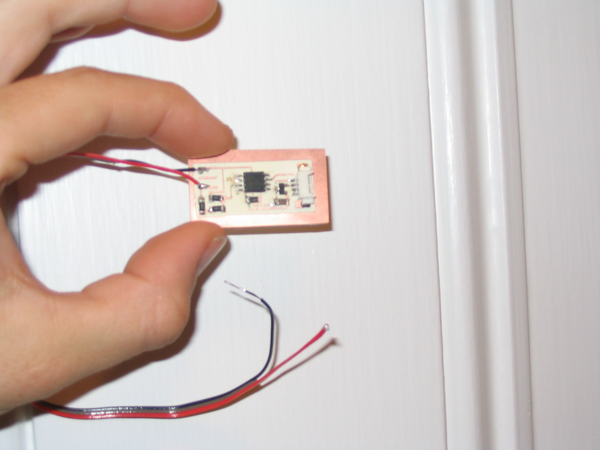
We cut out 2 of the boards on the Modela with no problems, and Tom stuffed them. Now we just have to work on code to make them "go"!
Thursday, November 3, 2005
Today we got some code written that we think will work, and we planned to program and test our chips. We had ENORMOUS trouble doing the programming! We kept getting the error message that the AVR was no responding. Finally, after an hour and a half and some help from Manu, we uncovered our stupid mistake. We thought that just having the serial cable plugged in to the chip provided it with power. NOT SO! A hello world board (designed to draw power from the computer it's connected to via the serial port) must be plugged in to the computer, AND a program (e.g. rx.py or echo.py) must also be running to power the chip. Once we figured that out, we were able to program the chip with no trouble. I later found out that that itself was no small feat, and was due to Tom's wonderful, actually-functional programming cable (see my week six rant about programming cables). We set to work debugging the code (assembly code, and code to print the measured voltage to the computer screen).
Friday, November 4, 2005
The dvm works! We used it to measure Vcc and the voltage output by a 9V battery, and both seemed to work.
Here are a few things we worked through as we wrote our code:
Assembly code
- We used Seth's measurer.dvm framework as our starting point. Looking at Neil's hello4.mic.asm microphone assembly code also helped very much, although the mic code is written for an ATtiny15, so it needed some modifications to work for the ATtiny13.
- Clearing the ADMUX, REFS0 bit tells the tiny to use Vcc as its reference voltage, while setting it (to 1) tells the tiny to use the 1.1V internal reference as reference voltage.
- Setting the ADCSRA, ADEN bit enables the ADC. For the finished HTMAA sensor, we think that this bit should be cleared if/when the sensor goes in to a mode that does NOT use the ADC, to save power etc.
- For our dvm, we do not want the ADC to auto-trigger; we want it to take measurements when we tell it to. So, we have to turn off the auto-trigger function by clearing the ADCSRA, ADATE bit.
- one thing came up that may affect the overall "HTMAA" project. When you set up an ADC pin to make measurements, you have to set 2 bits (ADMUX, MUX0 and ADMUX,MUX1) to let the tiny13 know which ADC pin input is coming in on. Either someone will have to check all the code once the final board is routed to make sure these are all right, or else we have to figure out a way to write in assembly code, "if dvmpin=PB2, then ADMUX MUX0&1 are such-and-such, and if dvmpin=PB4....". I don't know how to do that yet, but I'm sure it can be done.
Python Script to print measured voltage to computer screen
- We used Neil's hello4.mic.py script as the basis of this file, with several changes...Both Seth and Shani helped answer our programming questions (thank you!)
- We wanted the output to print continuously on the screen (until the user terminated the program), and the mic program runs for 10,000 samples and then stops. We changed the code for our purposes by changing the condition of the loop from "for i in range(10000)" to "while 1".
- We wanted the output to be a floating-point number, not an integer, so in the print command, we had to change the print command from %d to %f.
- We know that the ADC output is Vin*1024/Vref, so we had to multipy the output by Vcc and divide it by 1024 to find the correct input voltage to the dvm. That is the number we printed to the screen!
- If you are running Windows, you need to change '/dev/ttyS0' to a number corresponding to the COM port (serial port) your chip is attached to (COM1=0, COM2=1, ...COM7=6, etc.).
Sunday, November 6, 2005
Here are some of my concerns, and things I would like to improve on...
- Our DVM can only measure positive voltages (I think...?)
- We did not use the circuit Neil showed us in class last week, but made our own. I don't know if we could have or should have used that basic circuit - maybe we should, for consistency throughout the class. Otherwise the class board is going to be crowded with many many different circuits...We made something that works, but I don't know if it will be easy to integrate into the overall design.
- We want to think about adding some additional features, or expanding the range of things this sensor can measure (larger voltages? AC?).