|
|
|
|
|
|
|
|
|
|
|
|
|
|
|
|
|
|
|
|
The story in text:
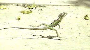
The objective of the basilisk lizard robot project is to identify what is special about the basilisk lizard, and then use the tooling and control strategies developed in MAS 863 to change the world for the better by capturing this function. This topic was also selected based upon my limited experience with Robotics (i.e., desire to try some) and the sensative design constraints presented by a problem with hydro rather than geodynamics boundary conditions. The fall back plan is a lizard that tries to walk on water, and can walk on land (ie, is waterproof, etc.)
Learning about Lizards:
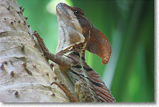
1. To begin, I determined what it is about the lizard that is particularly special. Initial considerations included a weight to foot form / size ratio, a unique leg motion, starting or cruising speeds, and an unknown factor no one has ever considered that has yet to be determined.
2. I read through a few papers on the lizard, emphasizing diagrams to speed up the process. A list of the reviewed literature is listed below. The lizard pictures are all screen shots of various excerpts that proved particularly informative. I learned that the lizard has an extremely long second toe, uses three axis motion to achieve purchase on the surface, and must be moving before taking to the sea.
Objective:
The goal by Monday the 18th is to have a lizard robot that can step off of a hard surface and onto a watery one, taking at least two steps on water.
|
|
|
|
|
|
|
|
|
|
|
|
|
|
|
|
 |
|
 |
|
 |
|
|
|
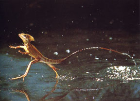
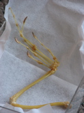
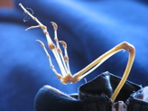
Lizard caught in motion. |
|
Diagrams of leg geometry. |
|
Surface boundary penetration. |
|
|
|
 |
|
 |
|
 |
|
|
|
Force distribution during stroke. |
|
Foot size versus mass. |
|
Toe shape and claw extension. |
|
|
|
|
Making the Model:
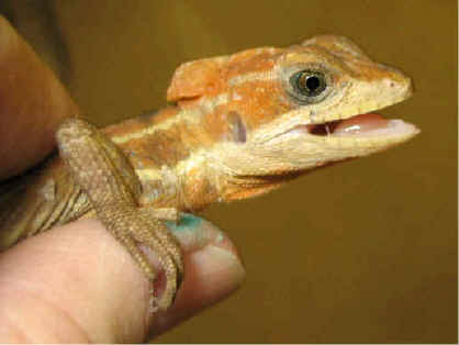
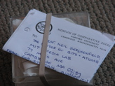
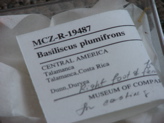
The first step proved to be a voyage to the MUSEUM OF COMPARATIVE ZOOLOGY at Harvard (after many emails to CMU's robotics lab, and a biomimetic design group at Brown. ) In the herptology department, I found a currator who very kindly provided a basilisk skeleton from 1928 for my review. I signed out the hind leg and foot for further study in lab.
My initial thought was to make casts from the bones, beginning with a polyurethane immersion process to make the mold, and then plaster case cast. Current intuition suggests that it may be better to make composite leggs that are lighter than the plaster would be as the joint will likely be too hard to control unless it is synthetic both in terms of material and design.
The body is not as essential as the legs, but need be light and sturdy. The body will also house the electronics inside of its belly. All boards will be fabricated using the vinyl cutter to ensure that they are as light and flexible as possible. The lizards exterior surface will be painted on, and fastened using the top portion of a ziplock bag to enable debugging and waterproofing. |
|
|
 |
|
 |
|
All images to the left are from the Harvard Museum. I signed a series of release forms to borrow the specimen. The image with a blue background is provided to give some sense of scale. The black in the image is the top of my paddock boot. |
|
|
|
Last look at the lizard. |
|
Clamps. |
|
|
|
|
|
|
|
 |
|
 |
|
 |
|
|
|
WaterJet cutting away. |
|
Garnet for the WaterJet. |
|
Someone else cutting away. |
|
|
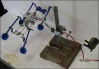
Building Process Outlined:
Structure: As is partially described above, the 'skeleton' of this robot will be made of composite materials. The base structure will be provided by hollow aluminum tubes or standard drinking straws coated in one or two layers of composites. The joints will be ball in socket or rod end ball joints. Quick-set epoxy will be used to enable rapid turn-arond on designs.
Body: The lizard skin will be stretched over a standard fine mesh window screan. A plastic or rubber skin will then be pulled over the srean, with zipper bag closures for easy access. The objective of the body is to keep the electronics dry and then also increase the surface area of the legs and body to enable it to push off of the surface of the water more effectively.
Controls: The legs will be driven by a set of stepper motors. Should this fail, a stardard drive will be used to break the laws of nature and see the leg make a 360 degree pivot at the hip joint.
|
|
|
|
|
|
|
|
|
|
|
|
|
|
|
|
|
|
|
|
|
|
|
|
|
|
|
|
|
|
SolidWorks pre-export. |
|
Control station for CAM . |
|
Working through the traverse. |
|
|
|
|
|
|
|
|
|
|
|
Trying to fill in the holes. |
|
The path finally works in Make. |
|
Sending to WaterJet in Process. |
|
|
|
Materials:
- 0.1 in aluminum tubing
- 0.1 in carbon tubing
- 1 box drinking straws
- 1 packet modelling clay
- 1 box ziplock baggies
- 1 window screen
- 1 2' x 2' sheet rubber film with adhesive backing
- 6 small bearings (1/8 in)
- Polyurethane casting
- Dragon Skin Silicone
- Mold Release for Urethanes
- Quick-Set Epoxy
- Fiberglass and Kevlar 2 oz fabric
- Epoxy based backing
- Copper film
- Componentry required for Hello Board for Stepper Motor
|
|
|
|
|
|
|
|
|
|
|
|
|
|
|
|
|
|
|
|
|
|
|
|
|
|
|
WaterJet at work. |
|
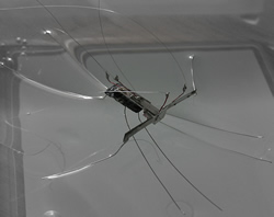
Lizard bits on the floor. |
|
|
|
|
|
|
|
|
|
|
|
|
|
|
|
|
|
|
|
|
|
|
|
|
|
|
|
Schedule:
- Monday: Find Basilisk Skeleton
- Tuesday: Build 'Skeleton' and reach point of articulation
- Wednesday: Complete Skin
- Thursday: Build Motor Control Boards
- Friday: Integration Exercise 1
- Saturday: Land to Water test 1
- Sunday: Website Completion and Debugging
|