Assembly Code Status:
I didnt have a board and components ready to start writing code so I used one
of the hello examples and soldered a few of my components to it in order to start
developing code. It isnt pretty but it did the job:
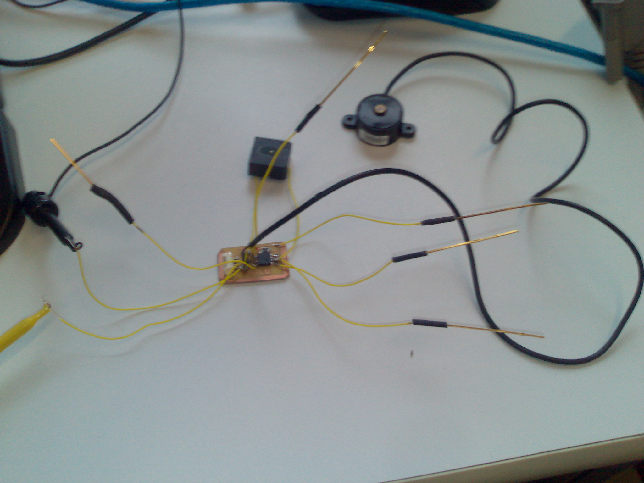
As I began developing I realized there was no chance inhell that I would be able to
get working code without having a debug interface to the MCU. So I attached a serial
cable ground to the ground on my board and the RX pin of the serial cable to a pin
on the MCU. (See image below).
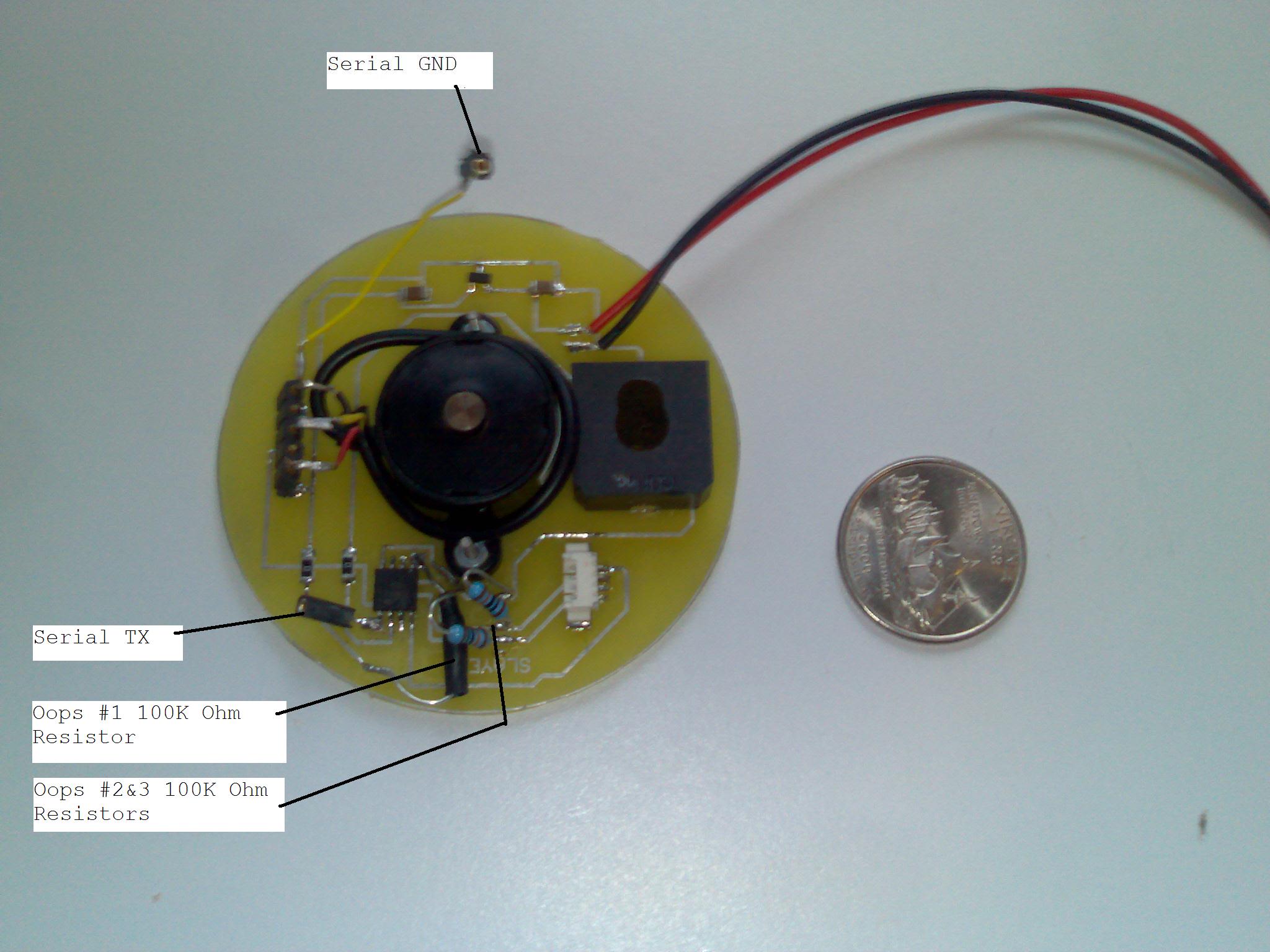
The first mistake that I realized that I made was that I was not keeping the RESET pin
high. To fix this I had to solder a 100K Ohm resistor from the VCC to the RESET PIN (Oops #1
on the image above).
Once I had the processor powered up I attempted to program it however I could not get it to
program after several hours of debugging I realized that the RESET pin was still low and headed
down the path of figuring out why. After a few days of gettign nowhere I started unsoldering
components from the board. Once I removed the load cell (the large round thing in the center of
the board) everything worked great. After some diagnosis I realized that the load cell was connected
to a pin that the programmer used. The load cell was always powered and was sending voltage to
the pin it was connected confusing the programmer. This is why I have a header soldered to the left
of the load cell so that it can be unplpugged during program time.
The next problem I ran into was the two pins that were to be reading the electrodes. They were constantly
high even though they had no direct voltage applied to them. I determined that because the 3 pins on the
molex were so close togther the voltage was capacitivley goign fromthe charged pin to the uncharged pins.
This is oops #2 & #3 on the image above.
I have all the code running on the final board, what remains is to tune the circuit to the
different cup sizes.