Assignment #6: Input Devices - Metal Detector
Metal Detector (using an inductor)
Things I learned:
How real metal detectors work
Basic Circuits
LC Circuit
Oscillators
Using a scope
AT45
A/D converter
Timers
Assembly Language
Really good understanding of the hello3 step response board/asm/py
The Process
Some background
Metal Detectors
Turns out there are many ways to make a metal detector, with varying properties of detection. There are about three ways to make an inductor based metal detector:
For this assignment the goal was to make a "hello-world" level metal detector, and trying to make it as simple as possible.
Resources:
XXX links XXX
Coils and LC circuits
XX wikipedia links XX
Proof-Of-Concept
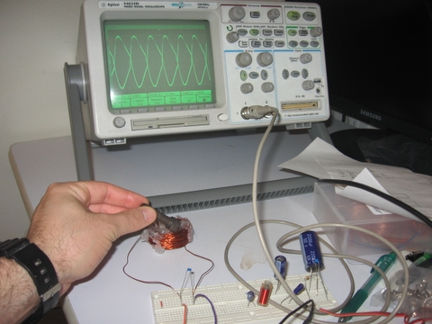
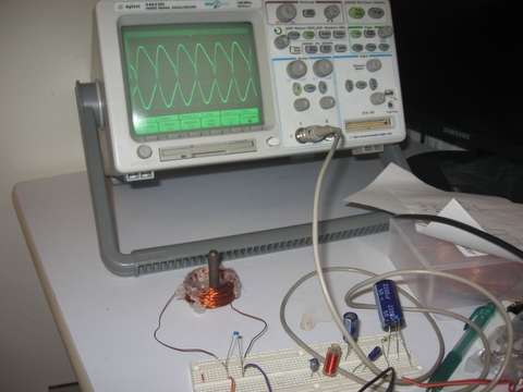
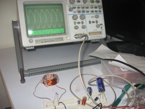
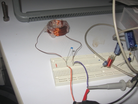
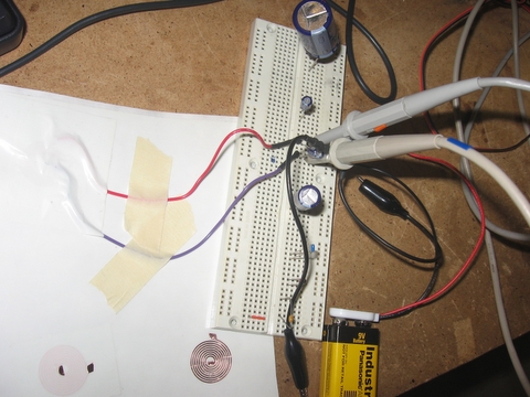
Before diving into the microcontroller board, I wanted to make a simulated "proof of concept" using a breadboard/wave-generator/digital-scope. The idea was to explore the different effects that metal can have on the output of an LC circuit (or an RLC circuit), so I can see how the detection can be done. It was important to have the simulation's parameters similar to the inputs/outputs I can do with the AT-Tiny45 microcontroller.
I simulated on a breadboard sine this made it really easy to connect different inductor/capacitor/resistor combinations.

Making the Coil
Frequency - oscillations of square waves desired frequency - since this is what I can generate with the AT45. It also has to be in a range that I can both generate in the microcontroller, and also read the relevant values in the right resolution/sampling rate.
Theory: frequency = 1/[2*pi*sqrt(LC)] - used this go get a feel for the right L-C combination, plus I wanted to get as low a frequency as possible, so that I can generate it and also read the output on the ATMEL micro controller.
Practice - after playing with many sizes and shapes of inductor coils, most of which seemed to have a very low inductance, I settled on a ~260mH (milli-henrey) coil.
~32Khz frequency had a good response, which is GREAT since it can be generated easily with the AT45. When getting metal close to it, the change seems to be mostly in the amplitude of the oscillating output, with no change to phase. This means that if we follow the peak of the steady output, we can detect changes in it caused by metallic objects.
The Board
I used the hello3 board design, with an AT45 chip.
Making the new board:
The assembly code
I Ramped up the chip to work with the highest clock frequency (default is max_clock/8)
Note that this affects the constant used for the serial communications.
There are changes that need to be made when moving from the AT13 to the AT45:
declaration (include)
Serial communications rate
command line: avrdude -p t45 -c bsd -U flash:w:<filename>.hex
Stage 1: be able to generate the 32khz signal from the at45
- played a lot with loops:
delay loop x cycles
turn on
delay loop x cycles
turn off
at first I got really low frequencies, and uneven square waves, something like this:
_____________________--_____________________--__________
When I was actually expecting something like this:
_--_--_--_--_--_
And I wasn't able to go higher than about 7khz...
Turns out it was the serial port transmission at the end of the infinite loop that was slowing me down. I removed it (the serial tx issue will have to be solved later though..) and this made the signal look as expected.
for x = 10 clock cycles (plus the length it takes to execute the loop actions)
I got a ~100Khz signal! GREAT!
for x = 30 I got about 40Khz
for x = 37 I got 32.8Khz on the scope, so this should be good enough for the first run.
11-5-06, stage #2:
Use my test circuit, and try to oscillate it with my AT45 board, measure externally with the scope and see if I get the same reaction.
* it should be noted that the signal from the AT tiny was not as clear as the one from the oscillator - the lines of the square waves had some noise on them..
* another thing that I noticed was that the oscillations at the aT45 output were at ~447mV amplitude, which is much less than the Vcc=5v that I expected...
I did get a waveform somewhat similar to what I expected, in the range of about 210-220mv amplitude. When I checked with my metallic bolt, I only got a ~5mv change...
Turns out that one needs to set a x10 factor for the incoming voltage measurements, so I actually had the right results!
I got to a stage where I needed to count the clocks it takes each command to execute in the delays of the output oscillations:
sleeploop:
dec counter ; dec = 1 clk
brne sleeploop ; 1 clk if condition false, 2 if condition is true
ret ; ret = 4clk
ldi counter, <n> ; ldi = 1 clk
rcall sleeploop ; rcall = 3 clk
==> performing this step would take:
ldi + rcall + dec*<n> + brne_false*(<n>-1) + brne_true*1 + rcall =
1 + 3 + <n> + <n> -1 + 2 +4 = 2<n>+9
making a: "sweep loop"
Defined several types of messages on the link:
; Message "headers" that go out before data is sent, to tell the python
; what state the microcontroller is at
.def SYNC_CODE = 11
.def ACQUIRE_CODE = 22
.def DATA_CODE = 33
; each "frame is set as follows:
; |'1'|'2'|'3'|'4'|TYPE_CODE|data_lo|data_hi|
Acquiring the signal:
; acquire peak loop
; goal: find the peak of the "saw" wave. I am assuming that the peak
; will remain at the same spot relative to the start of the wave.
; That was the observation from my tests with the scope & wave generator
;
; methodology: we want to sweep the range
right now we're only concerned with the positive voltage values and the positive peak.
So, up pulse width is a loop of a counter = 37 ==> ~ 83 clock cycles
Theoretically, we want to loop through 83 pulses, each time taking a measurement at a different place along the waveform, looking for the peak.
Attempt #1 - naive - we won't scan the first and last 9 clock cycles of the waveform. We'll assume the peak is in the range that we can scan.
so there are 2 ways to do the wave form sampling:
1) for each measurement, set up the circuit (run several oscillations at the right frequency until the systems setlles down), take a measurement at a different place along the waveform
pro - simple, no need for complex calculations for continuing the waveform at the correct requency
con - each measurement may take a long time since we need to have the output settle down before we measure....
2) make it so that we measure at different places within the waveform, without interrupting it, have the wavelength = pre_measure_counter + Measurement_time+ post_measure time
pro - no interruption of the oscillation frequency
con - may take more time to implement and debug
read about timers... will be good to use for the next phase of improvements...
About if/else/switch statements in assembly:
http://www.eventhelix.com/RealtimeMantra/Basics/CToAssemblyTranslation3.htm
///////////////////////
* Move x into Data Register D7
MOVE.L _x, D7
* Now compare x with y
CMP.L _y, D7
* If not equal branch to the else leg specified by label L1
BNE.S L1
* Moving 1 into z
MOVE.L #1, _z
* Branch beyond the if-then-else statement
BRA L2
* Else portion of the if-else statement
* Set z to zero
L1 CLR.L _z
* End of if-else statement. if portion of the statement executes an
* unconditional branch to reach L2. The else leg falls through into L2
L2 . . .
///////////////////////
