Assignment #7: Waterjet Cutter
"Hello Lock"!
or: How I Learned to Stop Worrying and Love the Waterjet Cutter

What I Learned:
Operating the waterjet cutter
Flexures
cad.py
Adobe Illustrator
OMAX
Layout
Make
SolidWorks/CosmosWorks
CAD Programs really hate to talk with each other
The assignment: Make a waterjet-cut flexure
My idea was to build a lock mechanism with the waterjet cutter. The lock is made of several layers that lock in a bolt and don't allow it to move. Only the right key can open the lock and release the bolt.
Cad.py and mathematical modeling
Setting up cad.py
I've been running cad.py on Ubuntu Linux. Aside from Python, make
sure you install the following packages:
python-image
python-imaging-tk
python-numarray
python-numarray-ext
cad.py and the concept of describing a drawing by a series of mathematical functions and transformations seems good for
Rapid prototyping - its easy to do iterations and change parameters of your design - all you have to do is change some predefined constant value (e.g. "material_width") and the drawing will adjust itself immediately (assuming we built our design correctly..)
A project with several parts that branch off from a common part, or depend on some common shapes and parameters - if we build our design hierarchically, it is easy to go to the "ancestor" part, modify it, and have the change be immediately reflected in all of the derivative objects.
Automatic layout functions - you
can design our own rules to layout objects, and the image layout
would change automatically as we change the conditions or the dimensions
of the parts.
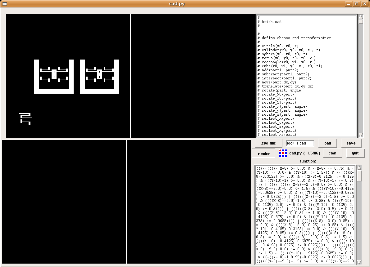
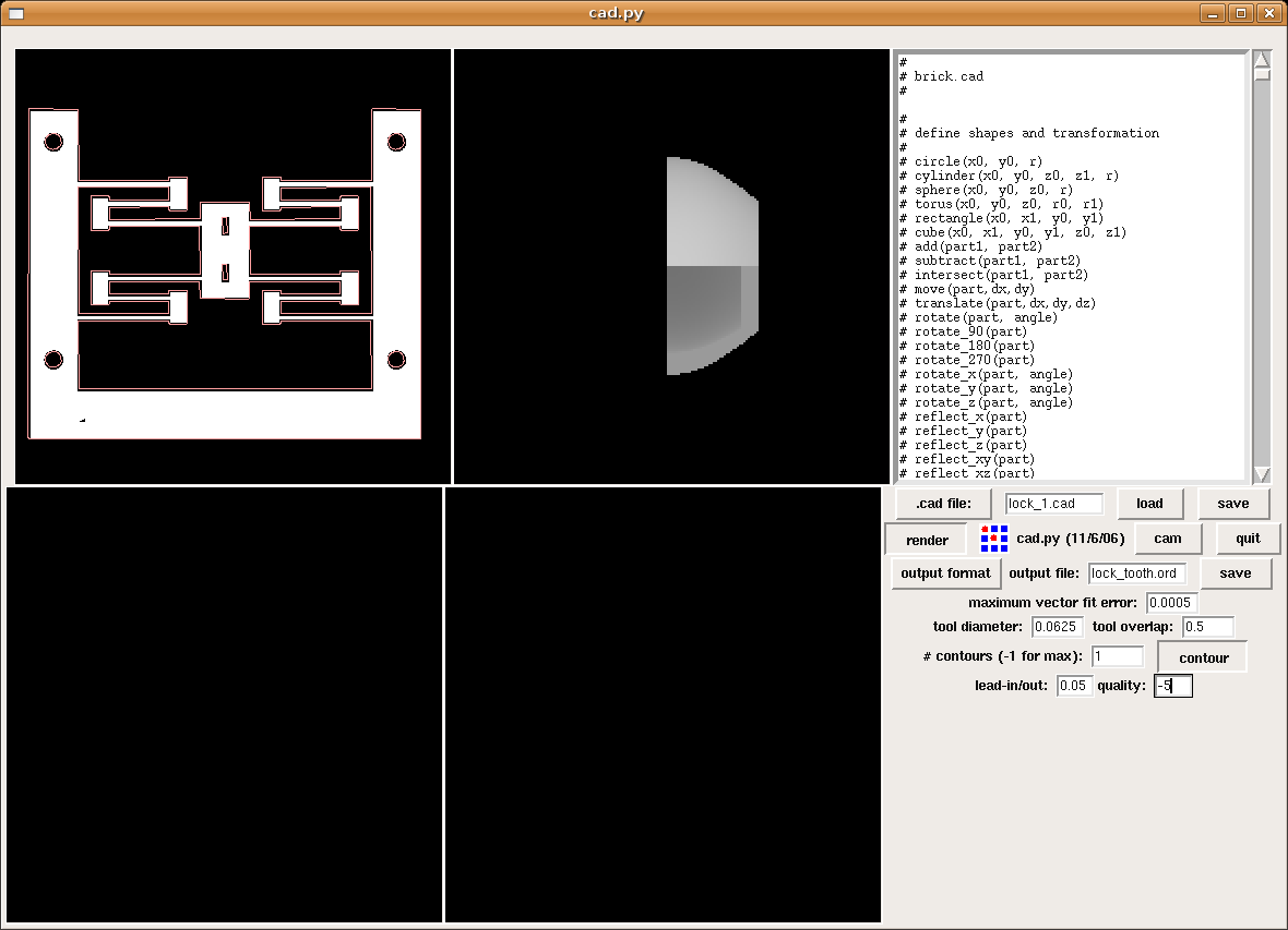
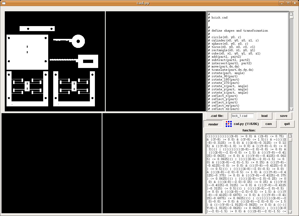
Some screenshots:


Assorted CAD and
Illustration software
I wanted to do some manual modifications and tweaking to the
final design. I was looking for a drawing program that's quick-to-learn,
intuitive-user-interface, and can save its drawing in a format that the waterjet
cutter's program (OMAX Make) can read. Apparently, none of the programs I've
tried actually achieves this.
The most problematic issue was exporting a drawing between the different formats. Even though most programs read and write .dxf files, there are great discrepancies between their .dxf formats. In some cases, only part of the drawing appears when opening it in another software. In other cases, the scale of the image changes. In most cases - the file just won't open...
Eventually what I did was to draw in
Illustrator, export to Corel Draw, and from there export to a format that OMAX
can open (Thanks for the tip, Thaddeus). Then fix and add things in OMAX.
Things to note:
Grouping objects and merging them is very useful when working within a drawing program, but it doesn't export well to other programs. Eventually I tried not to do any grouping, merging or adding of shapes, and save them to the last program in the chain.
Adobe Illustrator is very simple and
intuitive, and makes it easy to draw and manipulate simple shapes (mirror,
rotate, group, merge, etc.). Seems good for prototyping, and can save in
many file formats.
OMAX Layout
It has a very annoying user interface, but after some time you just get used to it.
Some notes:
To add water-jettable text, check out the SpecialTools menu --> Create Text (I've used tool-path fonts)
Don't forget to do cleanup drawing (SpecialTools menu) every now and then (make sure to save before doing so).
Cut quality - pressing the right-click button will give options to change quality for multiple objects.
Moving objects accurately- I've found it most useful to first move the the object to an existing point on a nearby object, and then doing a second move action, manually entering the relative (x,y) shift from that position.
To generate leads and traverses:
right-click "lead i/o" button, clear all existing leads and traverses.
auto-generate (quick)
if any leads are not the way you want them, change them manually at this point (assuming most other leads are OK)
After drawing a path, make sure the cut is on the correct side of your line!
Also make sure the cut sequence is correct so that there is minimum amount of movement of already cut out parts. In general start from the inside, and think about what can move and what is still supported.
Adding tabs to smaller parts:
select a place on the object where you don't mind having a bit of a rugged surface (from the tab leftovers), or a place you can later smoothen up.
partition a segment with "divide"
change the quality of the small segment to traverse (green colored line)
Copy .dxf and .ord to the "users" directory on the desktop of the layout computer. You never know when you'll need to do a quick change to the layout.
2) place many weights as close as you can. Vibrations are a problem. If you get
rough edges then your object is vibrating
3) remove cut out pieces as soon as they are cut out. Otherwise they can
potentially jam the waterjet head or cause to move your piece destroying the
work. What I ended up doing was to stop the waterjet, move it out of the way,
remove the piece and resume from where I stopped.
Using The Waterjet
Checklist
Safety glasses on
Load .ord file
set material details (for 1/8" aluminum or less, its enough to set the thickness, material type, and 0-2 jiggles to drill in)
Turn on water valve (90 degrees to the left = off, vertical = on)
place material + weights
lower head to the material (all the way down, a bit up until you feel the head starts moving again, and then 1/2 turn up)
zero both part home and user home on the program.
make sure there's enough garnet
raise water
I've had some runs where my part moved through the cut sequence. From then on I started putting really heavy weights and as many clamps as I could. This also means being really careful with the waterjet cutter head - so it doesn't hit any obstacle. Eventually I simulated a certain time-frame for the cut, saw where the head moves, and shifted the weights to make room. At the end of that sequence, I simulated again, and moved the weights accordingly.
Another good thing to do is to remove each piece that's completely cut out. Stop the waterjet after the cut is done, remove the piece, and continue. Sometimes I needed to move it forward or backward on the path so that the part can be removed. Then return the head to the right place and continue. Disconnected parts can rise up and damage the head, move the whole piece of material, or they may undesirably fall down to the garnet-abyss, never to be seen again.
The thinnest cut I made was 1/32"
flexure "rods" (connected between a stage and the base). They are a bit
delicate but allow for nice motion.