Assignment #8: Output Devices
LCD Screen + RGB LED (+ Development Board)
http://en.wikipedia.org/wiki/Big_Bertha_%28Howitzer%29
Things I learned:
Output Devices
LCD
LED
RGB LED
ATtiny
PWM
Communication between 2 microprocessors (unidirectional)
Eagle
Designing a Board + Schematics from (almost) scratch
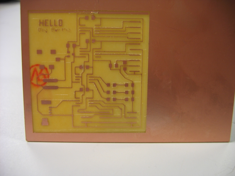
Big Bertha: development board
I wanted to make one board that will enable me to play with different input devices, output devices, and power sources. It should be generic enough to let me test different features for my final project without the need to make a new board. The third goal is to have some redundancy on it, so that if something breaks or mysteriously bursts into flames (hypothetically, of course), the board would still be usable.
The LEDs and LCD can also be used to display debugging information, so we can do assembly code debugging without a computer connection.
Perhaps this board can also be used for something like the class mult-imeter project.
BigBerthaBoard, BigBerthaSchematic, BigBerthaCMP
So what have we here?
4 Microprocessors: 2 for LCD output, 1 for RGB LED control, and 1 for input reception, serial output, and master for the other microprocessors.
Hello 7 - LCD demo board components
red, green and blue LEDs, including resistor for each LED. Source comes from VCC, and the AT13 acts as the sink
3 I/O connectors, each of them consists of 3 pads: Vcc, Gnd, and one I/O leg of the input microprocessor.
Battery pin connector
Backup - 2 additional plates for adding Vcc and Gnd wires
4 pin MOLEX connector (used mostly to allow serial input to the computer)
Notes (for next time..):
One of the I/O connectors is too close to the input AT13, which may make it hard to program the chip once its connected. I didn't connect it yet, and next time I would change its place.
It may be useful next time to put the LEDs farther out, so that I can play with different types of covers that would blend the colors
add power switch + reset button. Maybe even one per chip (so we can reduce power consumption)... Need to make sure we have Eagle schematics of them...
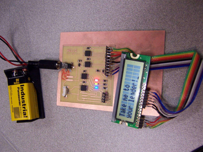
LCD Screen
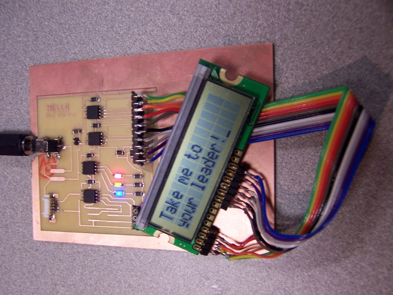
Based on the Hello7 class example, integrated into the development board.
From the Hello7 I learned how to set up a master-slave connection between 2 microprocessors.
RGB LEDs
I connected each of the three LEDs to a 1K resistor. The green one seems to shine less brightly. I plan to go to the specs of each LED, and put for each one the resistor that matches its specific max current.
The AT13 PWM can only output 2 different PWM signals, and I want to control each of the 3 LEDs independantly. I ended up doing a firmware PWM implementation. It essentially has a counter that defines the full wavelength time, and 3 counters, one for each LED, that defines what part of the wavelength the LED should be on or off. Results look good, and if we ever get to a stage where we need more processing power - we can always ramp up the processor speed by a factor of x8...
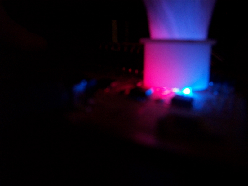
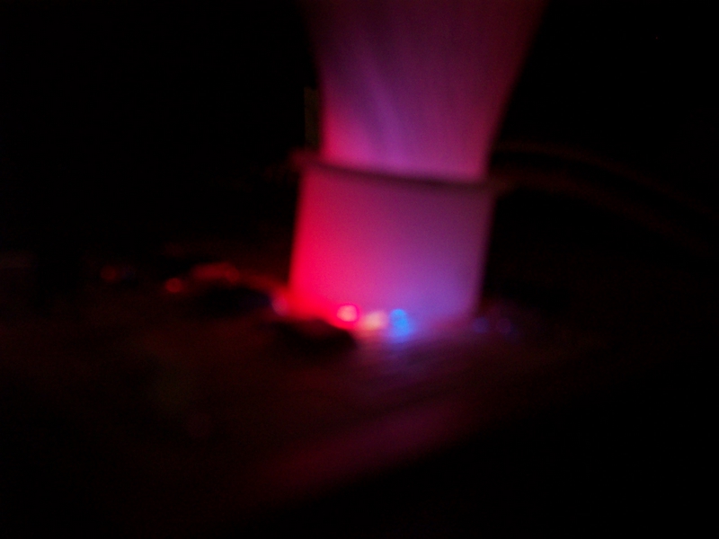
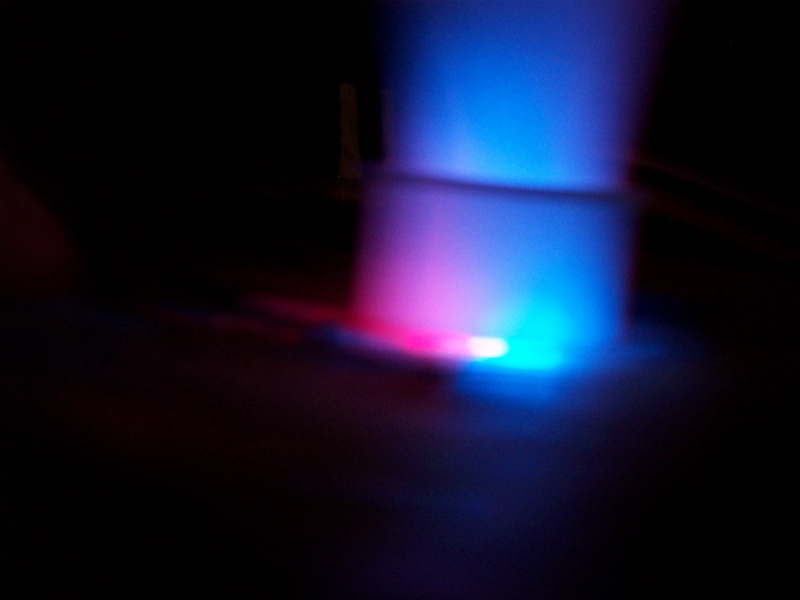
I played with some covers for the LEDs that would merge the colors, but couldn't find one that did it nicely enough. I think they are too far apart. I'll try to do a layout where they are closer together. I think I'll also want to compare with a single package RGB LED.
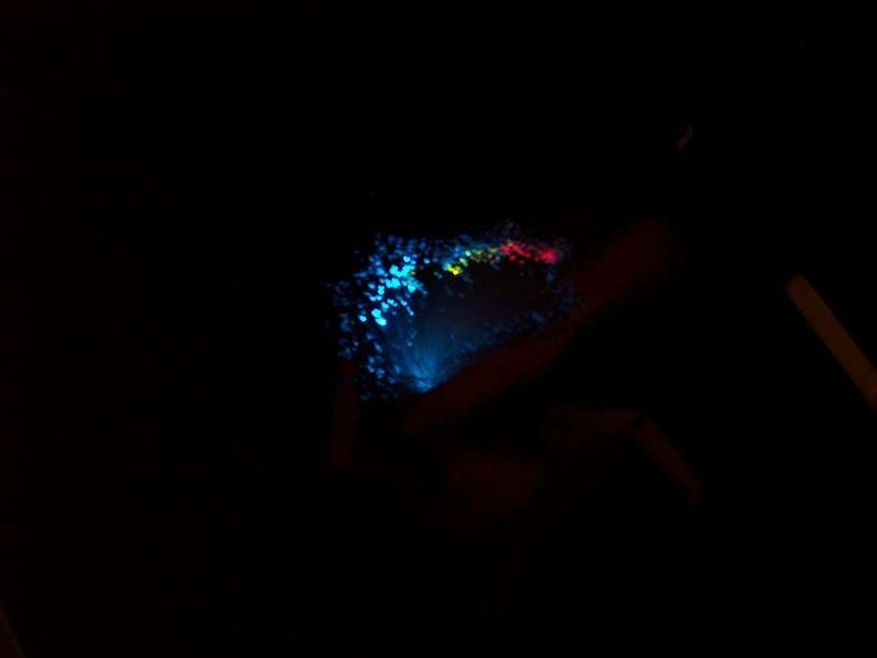
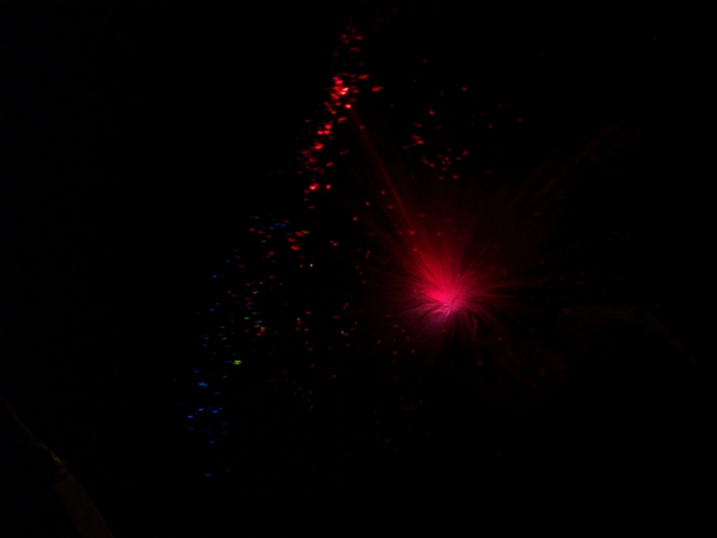
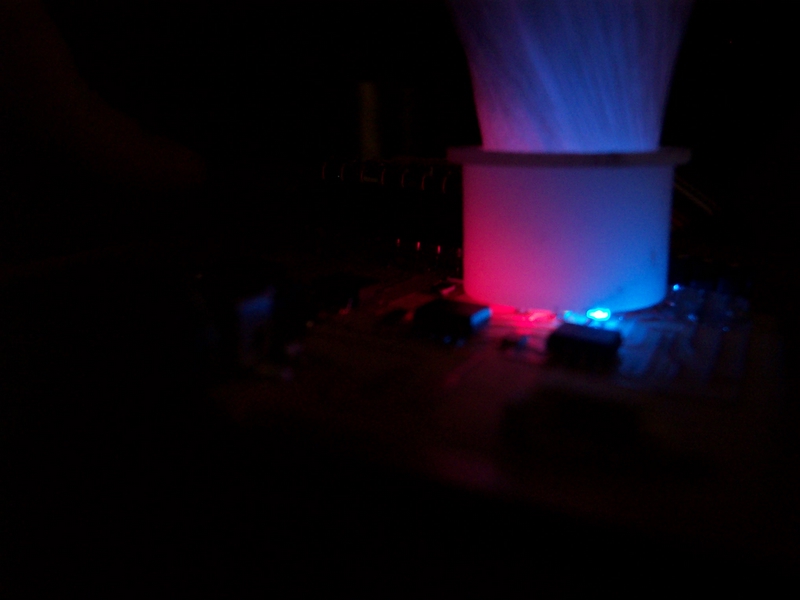
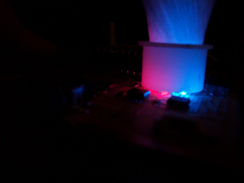
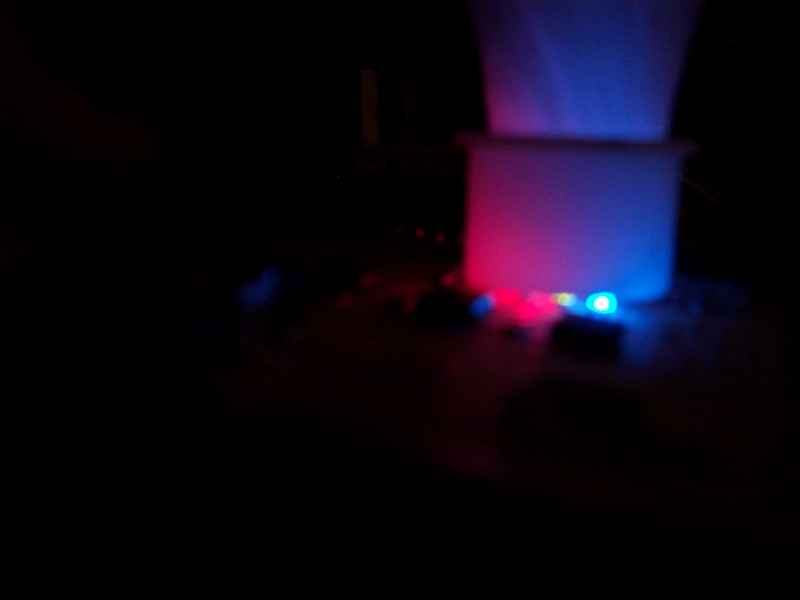
Big Bertha Disco-Mania (placing fiber optic cables on top of the LEDs)