Project 8: Output devices. Make
sound with the theremin using the PWM on the microcontroller.
I used a similar set up as for Project 6 (where I used the python sound
library sndobj to create sound) only this time I used the built-in
components of the microcontroller and a speaker to produce a
sawtooth waveform whose frequency (i.e. pitch) is dependent on
the capacitance it senses.
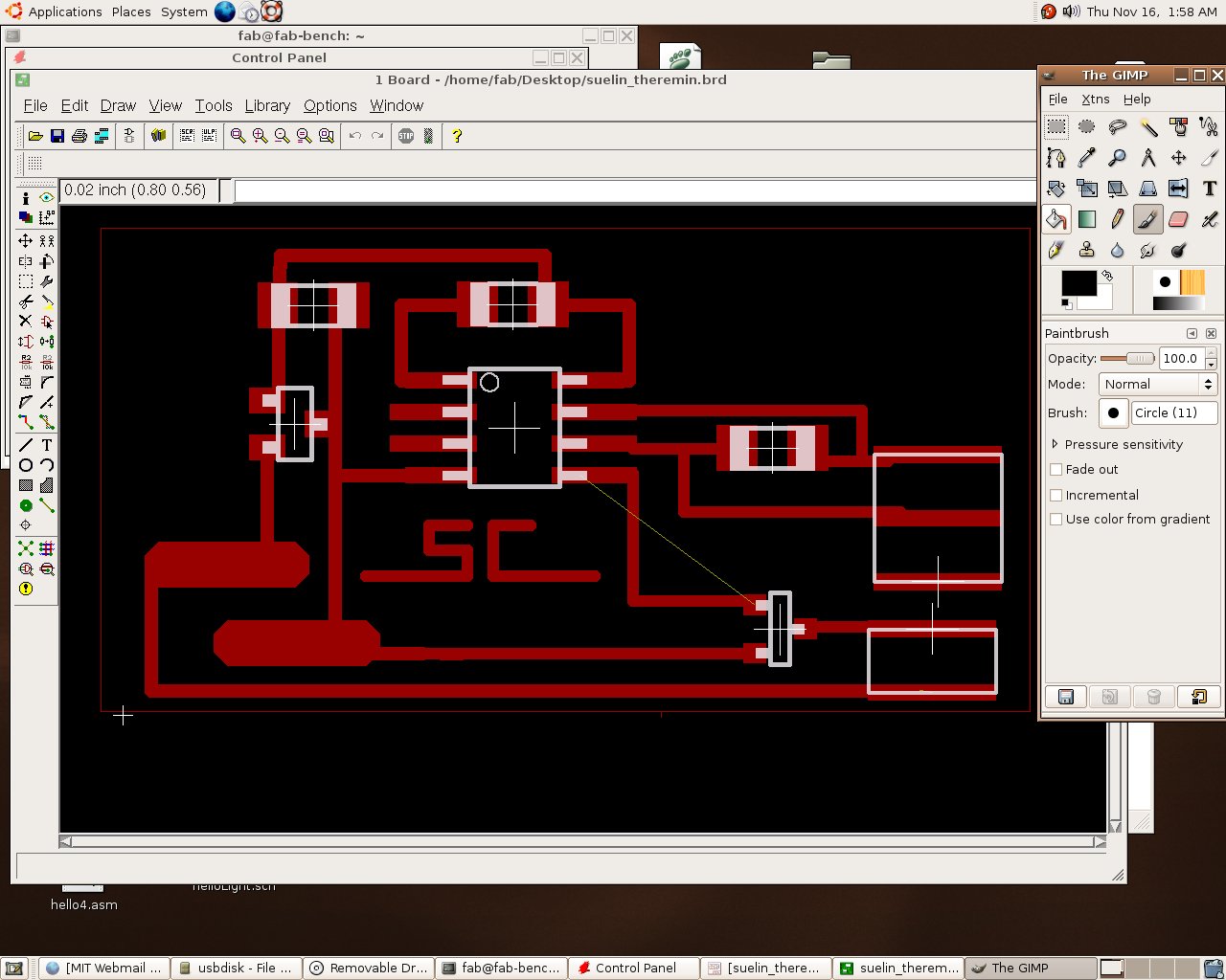
I had to redesign a board to incorporate the PWM elements.
I first wrote the firmware and made sure I could do everything with
just one microcontroller. I was able to do this by just switching pins from the
hello8 pwm code. The code, shown at the end, was difficult to write
because trying to improve the range of pitch coming out of the
microcontroller necessitated learning how to do arithmetic in binary.
I first plugged in my original theremin to see what kind of values it
was reading from the ADC. I then figured out what the best range was
(400-600 out of 1023) and used this part to determine the
frequency of the waveform.
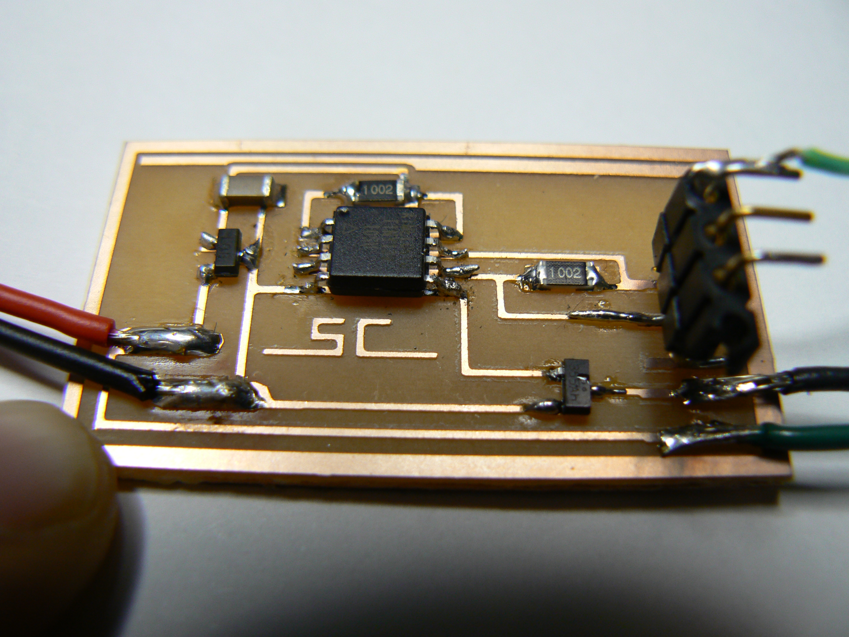
Here is the board layout and what the final setup looked like:
And here it is in action:
... Theremin Movie ...
Here is the assembly code I used:
; suelin.asm 11.14.06
; theremin
; based on Neil Gershenfeld CBA MIT 10/29/05
;
; definitions
;
.include "tn13def.inc"
.equ chargepin  = PB1 ; charging pin
.def temp = R16 ; temporary storage
.def temp1 = R17; temporary storage
.def delaycount = R18 ; sample update delay counter
.def delaycnt = R19 ; delay counter
.def pwm = R20 ; PWM value
;
.def uphi = R21 ; high part of ADC (ADCH)
;
;
; start of code
;
.cseg
;puts program at beginning of memory
.org 0
rjmp reset ; jump to reset routine
;
; took out all the putchar stuff
;
; routine to wait for sample to settle
;
.equ delay = 255
settle:
   ldi temp, delay
   settleloop:
      dec temp
      brne settleloop
   ret
;
; pwmdelay -- this sets frequency of sawtooth wave
;
pwmdelay:
   mov temp, delaycount
   delay_loop:
      dec temp
      brne delay_loop
   ret
;
;
; main program
;
reset:
   ldi temp, low(RAMEND) ; set stack pointer to top of RAM
   out SPL, temp ;
   ;
   ; init output pins
   ;
   ;sbi PORTB, txpin ; comm
   ;sbi DDRB, txpin ; "
   sbi PORTB, chargepin ; charging
   sbi DDRB, chargepin ; "
   ;
   ; init A/D
   ;
   cbi ADMUX, REFS0 ; use Vcc as reference
   sbi ADMUX, ADLAR ; left-adjust result (to drop the low bits)
   sbi ADCSRA, ADEN ; enable A/D
   cbi ADCSRA, ADATE ; disable auto-trigger
   cbi ADCSRA, ADPS2 ; set prescaler for /2
   cbi ADCSRA, ADPS1 ; "
   cbi ADCSRA, ADPS0 ; "
   cbi ADMUX, MUX1 ; input on ADC1
   sbi ADMUX, MUX0 ; "
   ;
   ;
;
   ; initialization for PWM
   ;
   ldi temp, low(RAMEND)
   out SPL, temp ; set stack pointer to top of RAM
   ldi temp, (1<