12/15: final project:
ambient temperature display
This project is an ambient temperature display.
ELECTRONICS
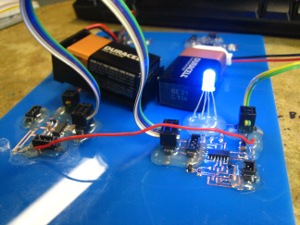
Learning from the previous input and output project, I took a structured approach to building the electronics. After some discussion with Siggi, I decided to make a controller board with my temperature input sensor and an output board that controlled an RGB LED and a motor. Elliott suggested that I devise my own communication, which is bases on the controller board sending a three bit binary signal and the output boards interpretting this signal to make the communication faster than serial.
Although I had learned how to use a stepper motor and A/D converter in a previous assignment, I had to do signigicant board redesign to (a) separate the input sensor from the output devices, (b) change to a DC motor, and (c) implement the communication. I kept a series of vinyl cut circuits as I progressed through the iterations to document my progress.
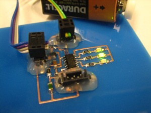
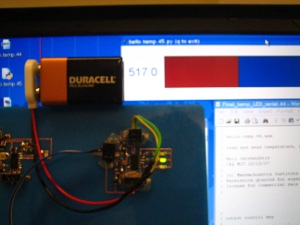
I took a step by step approach to building the board to make debugging easier. I built the control board with LED outputs for the binary signal and used serial communication to the computer to monitor the A/D converter.
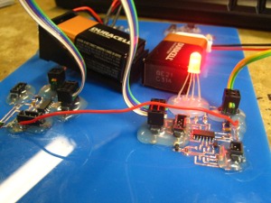
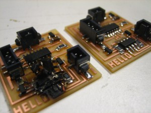
The output PCB board was straight forward, but I accidently made a transcription error when I converted Neil's H-Bridge board into Eagle. Unfortunately, this error was not too easy to catch. Additionally, Neil's original board did not have extra resistors which caused the H-Bridge to get very hot if the programming cable was left on the chip for too long. During one of my trials, I hooked up 18V (2 batteries) to the chip and set fire to the H-Bridge. My guess is that this fire was related to the lack of resistors. Here, you can see the scorched board next to a newly made board:
Here is a quick summary of the electronics:
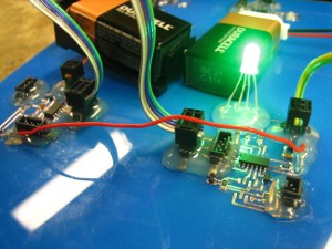
- Combination of hello.H-Bridge, hello.temp, serial communication, and my own implementation of an RGB LED.
- Communication by setting 3 pins high or low on a controller board containing the temperature sensor and interpreting these values by output boards (each output board contains an RGB LED and a DC motor).
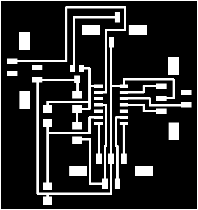
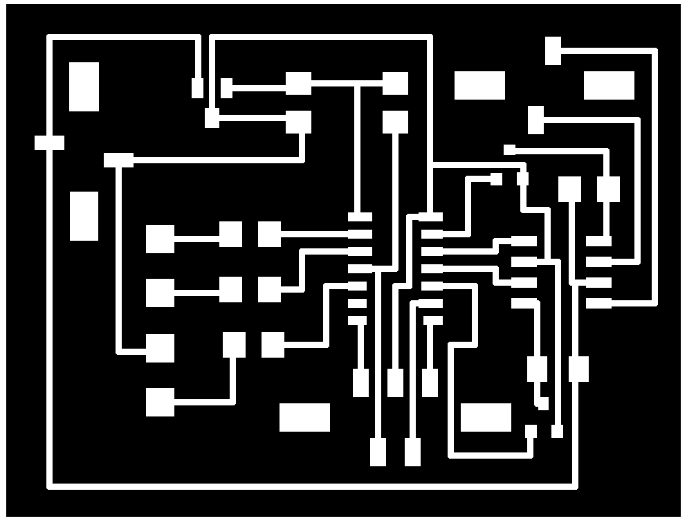
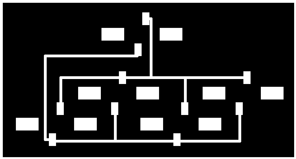
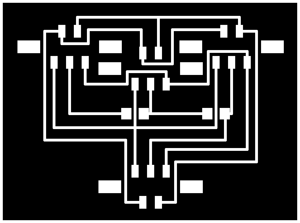
PCB BOARDS (exported from Eagle):
Controller Board
Output Board
Power Connector
Signal Connector
MECHANICS
I went through severl iterations for the mechanical design. My first design was a four bar linkage system where the DC motor was going to drive one of the bars. Ryan pointed out that the motor had to run fast if I was going to get any torque out of it, and that I should slow it down with be bulding a gearing mechanism. I tried doing so, but since I had never designed gears before, my gear ratio was too small and the gear teeth too large. Thank you to Jonathan for teaching me about spacers and lock washers which allowed the mechanism to move slowly. However, when I tried to drive the system with my motor, the gears often locked.
At this point, Ryan gave me several geared motors to drive my project. I redesigned my mechanism to be a two bar linkage (thank you Arthur), driven directly by those motors.
One bizzarre issue I ran into was that the motors wouldn't work when I screwed them onto my project. Kenny pointed out that if the screws are in too tight they jam the gears and prevent the motor from moving... I am not quite sure why anyone would design a motor in this way, but the project worked after including extra spacers.
Here is a quick summary of the mechanics:
- Laser cut, press-fit two bar linkage mounted on the shaft of a geared DC motor.
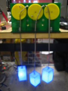
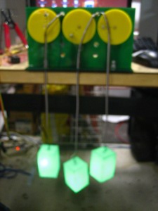
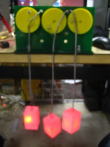
LEDs
I mounted the RGB LEDs in a clear, acrylic cube rastered on all sides and painted white on the inside. Painting the inside white gave them a nice glow and diffused the colors rather evenly.
The final project looked like this: