9/29 pcb fabrication, board stuffing:
hello world
MAKING THE PCB BOARD
Set up the Modela minimill:
Use double stick tape to secure the copper board you intend to etch in the lower left hand corner of the Modela grid.
Zero the machine - The machine should be in "View" mode. Press the up and down arrows simultaneously to zero the machine. Release the bit, move the bit up in the machine, move the bit to the lower left hand corner of the machine, lower the achine so that there is about one cm "give", release the bit so that it rests on the copper board, and tighten the machine. I used a 1/64 bit for etching.
insert photo later
Open cad.py and load the file with your circuit layout. I used hello.serial.45.cad found at http://fab.cba.mit.edu/about/fab/ for the layout of my circuit. Uncomment the "dpi" to be 500.
The code is initially set for low resolution viewing (200 dpi). Comment out the 200 dpi and uncomment the 500 dpi for high resolution for machining so that it looks like this:
#dpi = 200 # low resolution for previewing
dpi = 500 # high resolution for machining
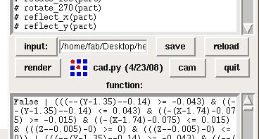
The first control screen will look like this:
Select the "cam" output format and then "render" to arrive at the following screen:
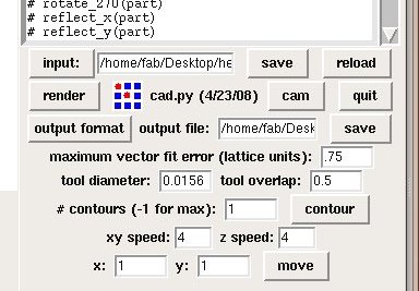
The Modela reads .rml files. Click "output format" and select .rml from the dropdown menu. For a 1/64 bit, the "tool diameter" should be 0.0156. The "# contours (-1 for max)" should be set to -1 to contour out the entire board (-1 makes as many countours as possible). THe "xy speed" and "z speed" should be 4 for the copper board we used for this project, but is material dependent. "x" and "y" should each be set to 1. Click "move" to begin milling.
A few useful linux commands I learned:
| process list | ps |
| extended process list | ps -aux |
| kill select processes | kill -9 process number -9: don't listen to it process #, e.g., 6319 |
PROGRAMMING THE MICROCONTROLLER
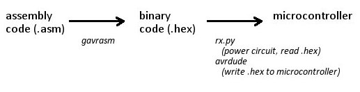
Generally, programming the microcontroller involves writing the assembly code (.asm file extension), translating the .asm file to a binary format (.hex file extension), and transfering the .hex file to the microcontroller. This involes the gavrasm and avrdude linux commands as well as rx.py as shown below.
Note on Linux. Here are a few commands I found userful:
| list all files and folders in the current directory | ls |
| change directories | cd e.g., cd Desktop/users/inna |
| override permissions | sudo |
| change permissions | chmod |
| permission to read, write, execute | 777
explanation: 4 = Read 2 = Write 1 = execute 4+2+1 =7 7 = R+W+E 6 = R+W 5 = R+E 3 = W+E Frist 7 Repersent Onwer second 7 Repersent Group and the last one represnt others |
| root directory | / |
| device directory (found in system root directory) | dev |
1. First, it is important that you have permission to use the system's serial ports. To do this, identify the system's serial ports and set the permissions to read, write and execute.
You can identify the system's serial ports by changing to the device directory, listing all the files, and identifying the serial ports.
cd /dev/
ls
When I did this, I found ports ttylS0 and parport0, and set their permissions to read, write, and execute. Please see the note on Linux commands for notation.

2. Download or write the assembly code for your circuit and save your work. The assembly file will have .asm extension. Make note of the folder where you saved your file.
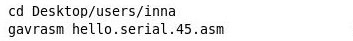
I downloaded the hello.serial.45.asm assembly code for the "hello world" circuit from http://fab.cba.mit.edu/about/fab/ , and saved the file in a folder with the file extension "Desktop/users/inna".
2. Convert your assembly code (.asm) to a binary format (.hex) that can be used to program the microcontroller.
You are now ready to program your circuit.
3. Connect the PCB board to the computer via the serial port (4 pins), though it is okay if you connect the parallel port (5 pins) as well. The serial port is for powering the circuit and reading from the microcontroller.
4. Power the circuit and read from the microcontroller by running the rx.py program, available at http://fab.cba.mit.edu/about/fab/ . rx.py is a python program and must be invoked through python. It takes two arguments: the serial port and the speed. (note: since this is a low powered circuit, it can get power from the serial cable parasitically. If you program a high power device, you will need an external power source.)
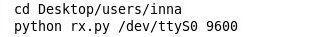
Do not close the terminal after you run rx.py - you need to keep the terminal open to continuously read from and power the circuit.
5. Connect the PCB borad to the computer via the parallel port (5 pins) if you have not done so yet. THe parallel port is for writing the program to the microcontroller. Open a new terminal window for writing to the microcontroller. Change directories so that you are in the same directory as the .hex file. Run the avrdude command.

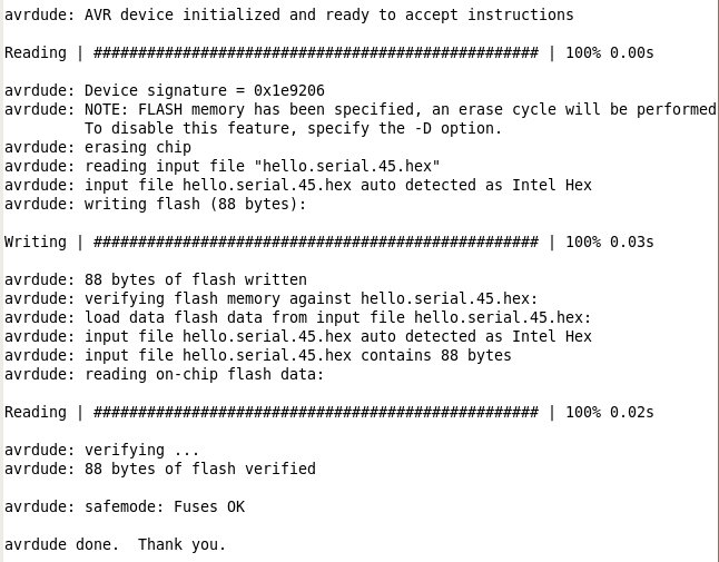
The notation pertaining to the avrdude command is below:
(-p) processor: tiny45
(-c) cable: bsd
(-U) memory type: flash
read about other command line options available at the avrdude documentation website
When avrdude is finished, your teminal should like this:
6. You will not see anything after you run the avrdude command. Remove the parallel port from the circuit after the microcontroller is programmed. You should see "Hello world" running in the terminal where you ran rx.py. In my case, I programmed my circuit to say "Demo or die!", so my terminal was as follows:
