Design a circuit boardThis is something totally new to me. I startet to make a tutorial on Sparkfun of a usb to serial converter, because I need that converter anyway for the hello boards later. Layout the schematic is not to hard to do, but to actually nderstand whats going on is something else. However, here is the schematic.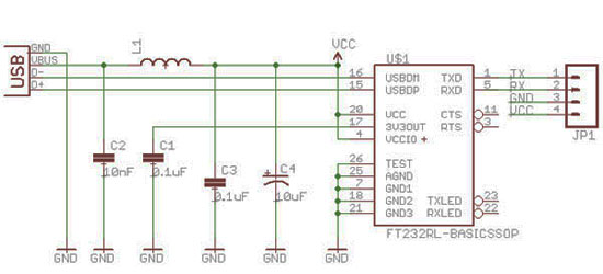 What I didnt like on their tutorial is the way they made the lay out. its really lots of space waist, ugly even 2 sidet design. Look at it 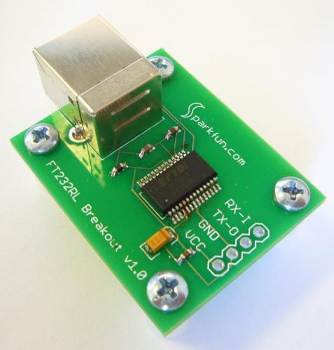 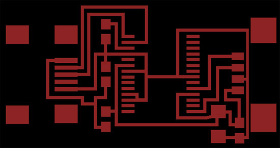
In cad.py using a 1/64 milling bit, it want mill out the entire board. I do need a smaller end mill. On the image below, you can clearly see where it goes wrong. 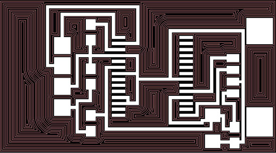 I am now waiting for the parts and the milling bits. Hopefully within 2 weeks, I can complete this board
back |
I am now waiting for the parts and the milling bits. Hopefully within 2 weeks, I can complete this board
back |
|