Initial Testing:
Before jumping into CAD I did some simple tests to validate the design. Through testing, it is clear that the spring stiffness determines how much force the spine can exert. Attaching springs to the ridged layers of the spine is crucial to restore the spines twist, translation, extension etc.
Design Overview:
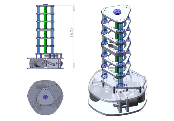
Three cables are used to move the spine in variable amounts of curve and compression. An additional twist axis transfers rotation through the spine using two telescoping universal joints (shown in green). Each of the three actuation cables, feeds through the spines segments, which are coupled by compression springs shown in translucent blue.
Twist:
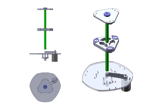
Torque is transferred through the spine using two telescoping universal joints. Encoding of the axis is done through a magnetic encoder shown below the base on a triangular bracket. The center of the spine serves as a pivot point for the universal joints and is not coupled to the DOF.
Spring Coupling:
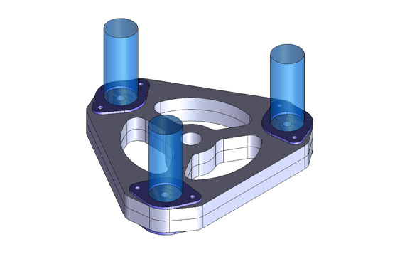
As observed in the initial testing, coupling each spring to the rigid layer is crucial to the operation of the system. A couple of methods are being kicked around, one being to weld or solder the spring to metal plates and bolt the plate to each layer. A second and slightly saner approach might be to use a similar bracket and washers to retain the spring.
Motor Unit:
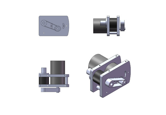
Three modular motor units are used to winch the spines cables down. The motor is coupled to the winch drum through a timing belt, which is tensioned through the rotation of the motor. A magnetic encoder gives the absolute position of the winch drum, eliminating the need for calibration on power up.
Before jumping into CAD I did some simple tests to validate the design. Through testing, it is clear that the spring stiffness determines how much force the spine can exert. Attaching springs to the ridged layers of the spine is crucial to restore the spines twist, translation, extension etc.
Design Overview:
Three cables are used to move the spine in variable amounts of curve and compression. An additional twist axis transfers rotation through the spine using two telescoping universal joints (shown in green). Each of the three actuation cables, feeds through the spines segments, which are coupled by compression springs shown in translucent blue.

Twist:
Torque is transferred through the spine using two telescoping universal joints. Encoding of the axis is done through a magnetic encoder shown below the base on a triangular bracket. The center of the spine serves as a pivot point for the universal joints and is not coupled to the DOF.

Spring Coupling:
As observed in the initial testing, coupling each spring to the rigid layer is crucial to the operation of the system. A couple of methods are being kicked around, one being to weld or solder the spring to metal plates and bolt the plate to each layer. A second and slightly saner approach might be to use a similar bracket and washers to retain the spring.

Motor Unit:
Three modular motor units are used to winch the spines cables down. The motor is coupled to the winch drum through a timing belt, which is tensioned through the rotation of the motor. A magnetic encoder gives the absolute position of the winch drum, eliminating the need for calibration on power up.

