Victor Vina
Fab Lab Bcn
<- Home
Input Output: Dome
Assignment: Connect an input device to an output device
Responsive environment design for parametric dome.
assisting Marta Male at IaaC.
This page documents the interactive system. For further info about the design and construction process refer to IaaC's blog.
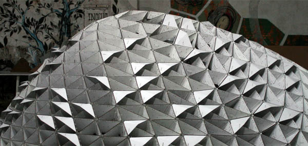
The studio, led by Marta Male, consisted on the fabrication of a parametric dome. I lead one of the students' teams in charge of adding interactivity to the construction. Out of the options discussed by the team, it was aggreed to use light as the output of the responsive environment, and presence, movement and sound as the inputs.
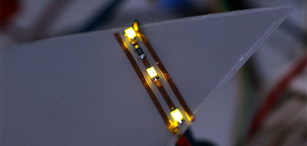
Research of lighting posibilites using the vynil cutter to create led strips on the parametric modules.
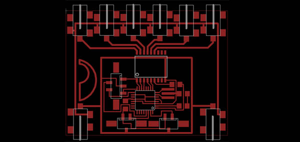
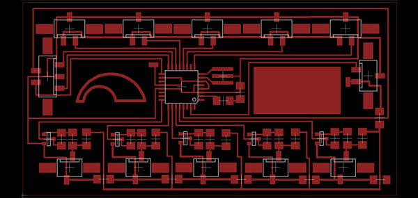
A daisy-chainable output board was designed to fade the led strips. Each board can fade six strips, so we produced 4 boards for a total of 48 strips, each led strip counting 40 leds. Each board has input and output 3 pin MTA connectors for data and DC connectors for power. It's based on the ATmega88 and the ULN2803A darlington array (while this IC is not usually stocked at the lab, it's useful for driving big loads -sinking 500mA on each output, 50V max- with full protection). While a simpler version of this board could be made with the ATtiny44, hardware PWM it's needed to avoid flickering at low frequencies, something achievable in normal pins only in assembly, as any other time critical application. The darlington array can also be substituted with 6 NPN mosfets stocked at the fab lab.
-> Dome driver board Eagle files: domeDriverBoard.zip (5k)
AVRs were programmed in C, and the hex code uploaded with avrdude through the ICSP header. The RS-232 protocol was set up with a baud rate of 115200 bps and a handshake of 4 bytes. The AVR updates its PWM pins with the first 6 bytes after the handshake and passes along the rest of the bytes through its DATA OUT header. A differen approach would involve all bus boards sharing the same serial line, and using an extra byte to identify the destination node.
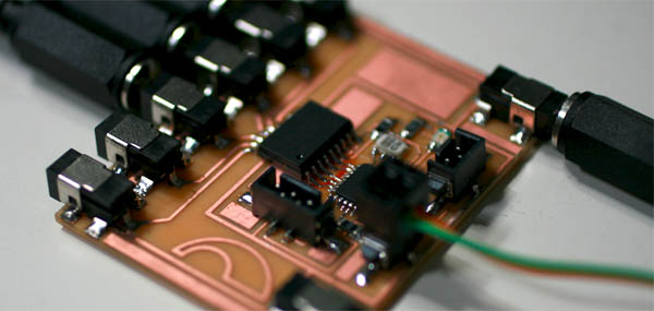
A second input board was designed to connect five electret microphones (for sound detection) and five ultrasonic range finders (to detect presence and movement in the space).
-> Dome sensor board Eagle files: domeSensorBoard.zip (3k)
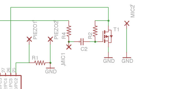
To detect sound, a simple circuit found here was used, using a NPN transistor and a few resistors to amplify the voltage from the Electret. While it works ok for detecting thresholds volumes, Hello boards mic implementations with the t44 and t45 offer way more fidelity and resolution. As the system was going to be run from a central box, a USB mic was finally used to acquire high quality sound.
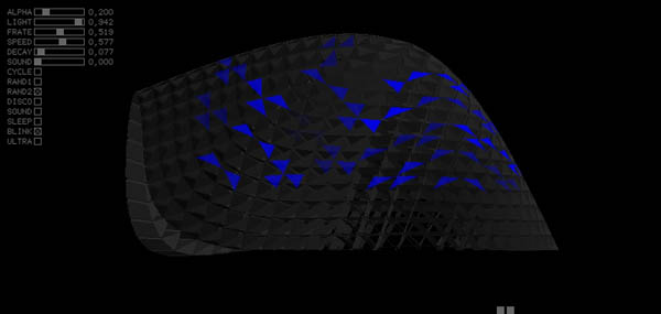
Software developed with Processing-Java was used to transform enviromental changes into light patterns. The software communicated with the input and output boards through RS232-USB and allowed real-time changing of patterns through a simple GUI. Basic behaviors responded to movement within the space. Sonia, a Java library was used to perform real-time spectrum sound analysis.
-> Processing source code: domeSoftware.zip (45k)