This was my first foray into PCB design, and so I had some difficulties interpreting the circuit diagrams as well as soldering the board.
The first step was getting my laptop to play nice with CBA's milling machine. At first I tried a Mac laptop since most other people were using Macs, but we had trouble running cad.py so I switched to my Vista laptop. This was actually quite simple to use. I already had Python 2.5 installed on my computer, so if you don't have that you'll have to install it first. I have 64-bit Vista, but I installed Python and the other packages as 32-bit programs.
The steps I followed were:
Now you should be up and running with cad.py. Depending on what flavor of Python environment you have installed you'll have to run cad.py differently, but with the Python IDLE GUI I first open python, then in IDLE open the cad.py file, then just select Run->Run Module to run the program. Open your CAD file (I used hello.serial.45.cad). This is the diagram of the board that will be milled.
Press the "cam" button, and click on the output format and choose ".g (G Codes)". Here are the output settings you'll want to change:
Now press the contour button. This will do the final rendering of the PCB. Save the output file, but change the file extension to ".gcode" instead of ".g". Now you need to install ReplicatorG. I used version 0.8 for Windows. Unzip the folder, and then replace the machines.xml file in the top level directory with this new file so that it will recognize the milling machine.
Now we need to get the drivers for the milling machine working. ON VISTA, YOU DO NOT NEED TO EXPLICITLY INSTALL ANY DRIVERS! This caused me some frustration, but what you need to do is turn on the milling machine and simply plug it in through USB to your computer. Vista will be able to automatically load the drivers (it will look like there is only one at first but actually there are two, so just be patient). This takes at least 20 minutes and you have to leave the machine plugged in through USB the whole time or the driver installation will stop, but you only need to do this once, so it's best to do when no one else needs to use the machine.
Now that the driver is installed, open up ReplicatorG. It'll probably throw an error like "Old firmware detected" when you open up but just ignore it. Make sure the correct machine driver is selected by selecting Machine->Driver->MtM PCB Mill. Open up the GCode file that you just created. Make sure the file is long. If it's only a few lines, you probably didn't contour it in cad.py.
You're almost ready to roll. The next step is to get the piece of copper that you're going to mill and tape it down onto the flat panel of the milling board using double sided tape. I put two long strips of tape along the underside with about a half an inch sticking out so it'll be easy to pull up after milling. The tape is to make sure the board doesn't move while it's being milled. Now in ReplicatorG code to Machine->Control Panel. This zeroes in on the start position for the milling process. The origin for cad.py is the lower left hand corner, but you should leave a little bit of space.
Now you're going to move the milling head into place. Set the motor speed to 255 before you actually move the head using the control panel. It's also important to remember that when you're doing an X or Y move you can use a 10mm step (jog) size, but for Z you should use more than 1mm because if you move it too close to the milling panel it could break the machine. Also once you get Z pretty close but not touching the copper you need to loosen the screw for the milling head and let it drop down to touch the copper. Then tighten it back up again. Press the "Set Zero" button and you're all set. It's best to use the Z buttons to raise the head an extra millimeter or two after you've set the zero point so that when you start milling it doesn't prematurely scratch the board.
You're finally ready to mill the board, so close the control panel and press the "Build" button. Now it'll start milling, and for me the process took 10 minutes, although it can take up to 20. When my board came out there were a few imperfections (rough edges) to the milled portions of the board, so I used my fingernail to scrape it clean. I was later told that getting oils from your hands onto the board can make it harder to solder, so it was suggested you use a stiff nylon brush to scrape it if you have one available.
Next came the soldering, where I have next to no experience. I didn't even know what components I should be soldering, as the diagram in cad.py was fairly opaque to me. Here's the basic code for understanding what letters mean what:
| Letter | Meaning |
| 5V | Voltage Regulator (upper label is IC2) |
| C | Capacitor |
| GND | Ground |
| R | Resistor |
| Rx | Receive Line |
| t45 | Atmel Tiny45 Processor |
| Tx | Transmit Line |
Soldering the small parts on first seemed like a good way to go, and since the connectors are normally farther apart you have greater margin for error. When soldering on the processor, however, I had trouble keeping the pins separate since the solder from the different pins kept getting stuck together. Using the copper wick I was able to eventually get all the pins separated, but it took about half an hour.
So now that the board was done it was time to make cables. I opted to only make one board mostly due to time constraints, and I was already fairly overwhelmed from soldering a single board. So I had to make two cables: one 4-wire serial cable to power the board and one 6-wire parallel cable to program it. To make cables you just need to tear off of the larger cable spool the number of wires your need (I had one 4-wire cable and one 6-wire). You can clamp on the connector to the board pretty easily, but as a convention I make sure that the ridges on the connector are always facing inwards on the board.
When you get the connectors for the PC side, you have to make sure that the wires will stay in place. This involves you basically pushing the wires onto the connectors using your nail or a screw driver. I always left plenty of cable coming out the other side, and this was really helpful when I wanted to confirm whether or not the cable was working. Here's the diagram for the parallel cable:
       plug                 DB25
    MISO (1)   ------------- 10
       V   (2) ------------- no connection
 --  SCK (3)   --- cable --- 8
 -- MOSI   (4) - direction - 9
   RESET (5)   ------------- 7
     GND   (6) ------------- 18

   plug               1   4   3   5     6
   DB25  13  12  11  10   9   8   7   6   5   4   3   2   1
   DB25    25  24  23  22  21  20  19  18  17  16  15  14
Basically the way to read this is that the first wire connects to connector 10. You can find connector 10 by looking at the bottom two rows, which represent the parallel connector if you're looking at it straight on, with each number representing the position of the pin. To figure out which wire is number 1, if you looked at the inside of the connector that's clamped onto the other end of the cable, the connectors would be arrayed in an alternating pattern that looks the way the numbers are arranged.
Now we have to make the serial cable:
      plug                 DB9
    GND (1)   ------------- 5
 -- DTR   (2) --- cable --- 4
 --  Tx (3)   - direction - 3
     Rx   (4) ------------- 2

   plug      4   3   2   1
        DCD  Rx  Tx DTR GND
          DSR RTS CTS  RI
   DB9   1   2   3   4   5
   DB9     6   7   8   9
You make this in essentially the same way as you did above, except now there are only four wires that you need to worry about. Remember to CLAMP THE CABLES TIGHTLY USING A WRENCH! This will save you headaches later.
Now you need to program the board. This is very well documented by Inna Koyrach here.
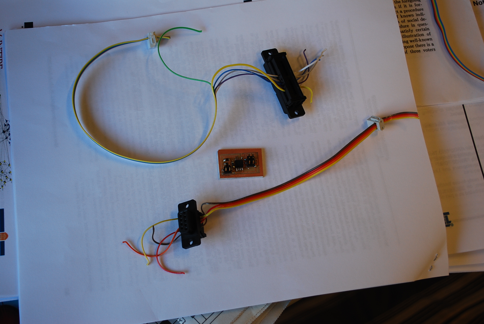
I actually had an error the first time I tried to run this. The board was successfully programmed but verify failed. I was worried that I was going to have to redo everything, but I just hadn't clamped the parallel cable tight enough. After I reclamped it everything ran perfectly. Here's a picture of the finished system for your viewing pleasure: