Step 1: Generate the bits
For the first step, I got cad.py running and generated the toolpaths
for the milling machine. This part is pretty easy--just follow the
instructions embedded in the cad file.
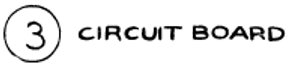
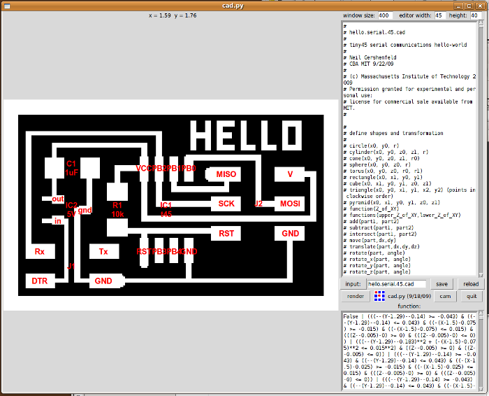
The first photo shows the board itself, without any tool paths. The
the second shows the path for complete material removal with a 1/64 inch
cutter.
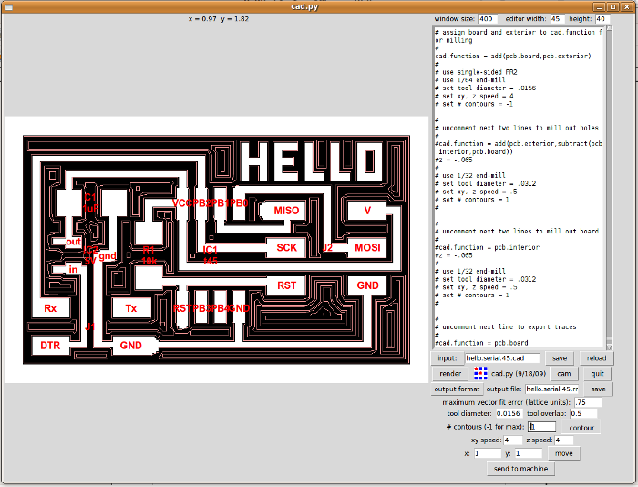
Step 2: Mill the boards
The next step was to actually mill the boards.
I stuck the raw PCB on the mill bed with double sided tape, and then
adjusted the Z axis so that the end mill just touched the board surface.
Once the machine was set up, the actual cutting took about 5 minutes
plus another minute or so to mill the board outline.
Step 3: Stuff it
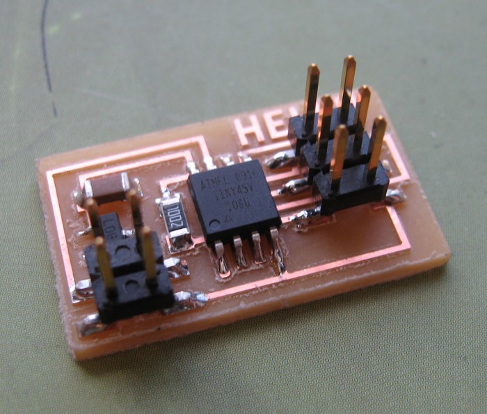
With the board machined, it was time to solder. I started with the 10K
resistor next to the AVR. It looked like it would be difficult to do
that one after the AVR was soldered. After the resistor, I did the AVR,
the voltage regulator, the capacitor, and finally the two connectors.
Step 4: Load the code
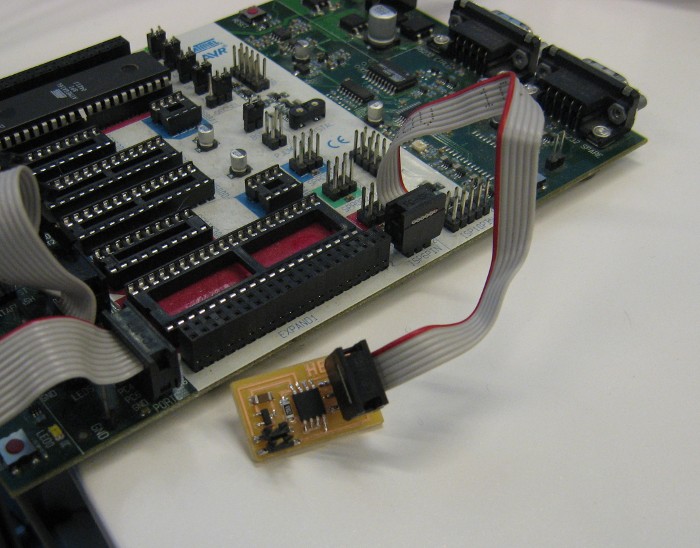
I used a Atmel STK500 programmer to load the code into the AVR.
The proper incantation for avrdude with this setup is:
avrdude -p t45 -P /dev/ttyUSB0 -c stk500 -U flash:w:file.hex
One cool thing about using the STK500 is that it provides power over
the 6 pin ISP connector. That means you don't also have to connect
the 4 pin connector to load the code.
Step 5: Building the cables
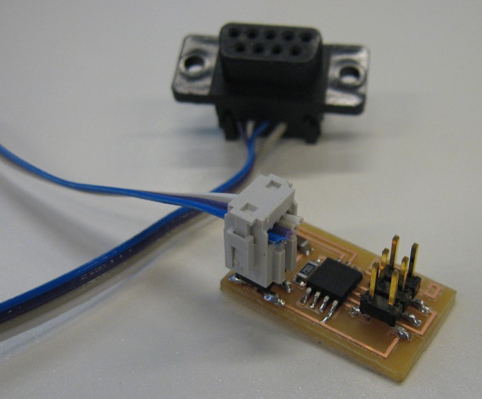
I had some trouble building the serial cable using the IDC connectors.
Some of the DB9 connections were intermittent. My solution was to
solder the connections at that end and then apply a little hot glue for
strain relief. So far, this has worked well.
Step 6: Plug it in
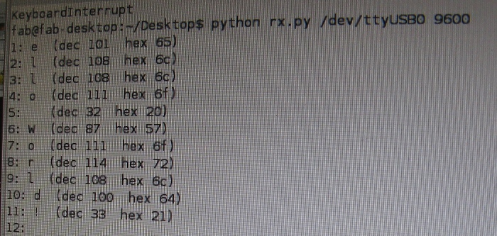
With board programmed and the cable built, all that was left was to
plug the board in. DTR was set, and a happy fountain of 'Hello World!'
sprang forth!
Over and out.