
Step 0: Concept
I recently discovered a couple of projects that use LEDs both as output
and INPUT devices simultaneously. Thus for the input project, I
thought it would be fun to build a board that uses LEDs to sense light.
I also wanted to put my new Tiny13 bootloader to the test, so you'll
find there is no 6 pin ISP header on my board.
The folks at the Mitsubishi Electric Research Labs have a technical
paper on LED sensing here.
Step 1: Schematic
My favorite tool for schematic capture is an open source tool called
gSchem.
I've used Eagle in the past, but I ultimately grew frustrated with
its interface (buggy on linux) and its design size limitations.
Here is a screenshot showing part of the schematic for my circuit.
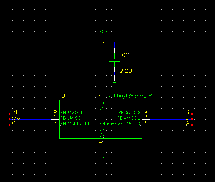
This is the full schematic.
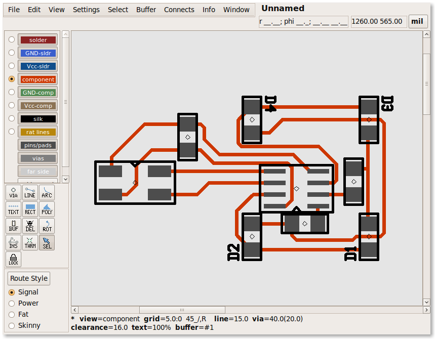
Step 2: Layout
I use another open source tool called PCB for layout. Here's what it looks like with my layout:
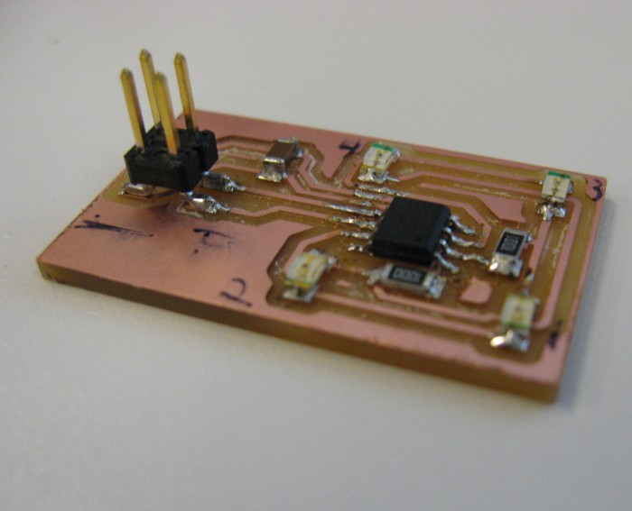
Step 3: Build
I milled my board on the Modella and populated it. I brought in some
lead free solder from home and used it to assemble by board. I had
no trouble using it with my iron set to 650F.
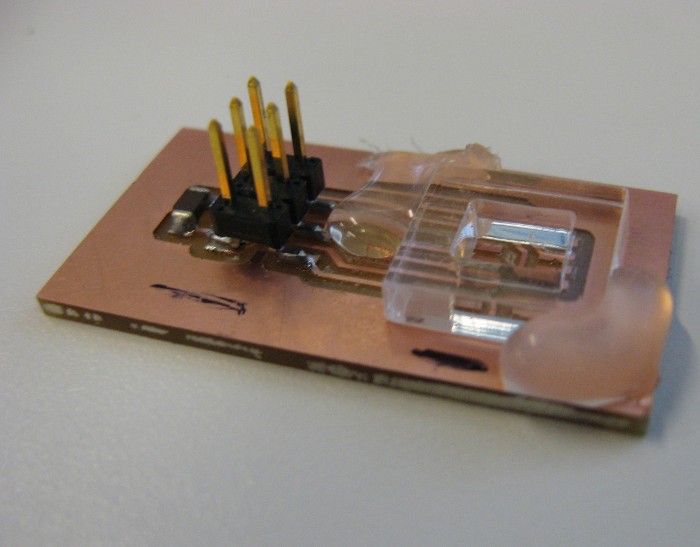
Step 4: Rewind!
Because my board has no 6 pin ISP header, I have to load my bootloader
code into the Tiny13 before soldering down the AVR. Well, I didn't do
that. So off came the Tiny13, and this time I remembered to program
it with my nifty SO-8 programmer board before soldering it.
Step 5: AVR Code
I wrote two major code chunks for my board. The first was a software
UART written in C. Abandoning assembly code made thinking and coding
easier in general, but it also meant I couldn't reuse the existing UART
code.
The second major piece implements the LED light sensing alogritm
described in the MERL technical article linked above. It proved
challenging to get this part working well, as I had no idea what
the approximate LED capacitance charge/discharge were and connecting
my scope drastically altered the waveforms.
There was severe cross talk between LEDs 1/2 and LEDs 3/4. As a result,
I ended up only doing sensing with LED1 and LED3. This works reasonably
well, but I the circuit is still pretty sensitive to stray capacitance.
You can download the full AVR code here.
Step 6: Host Code
This week Neil challenged us to create something other than a raw text
host interface. I used python, and the cairo vector graphics library,
to draw two translucent circles whose diameters vary with the output
of the two sensors. Here's what it looks like:

The code is here.
Over and out.