Hello World Board
PCB design, fabrication, assembly
>> Link to documentation of the Modela milling machine
Programming the board using a Keyspan serial to USB adaptor and a AVRISP mkii programmer. For whatever reason it did not work from my MacBook, but it worked fine from another Mac laptop.


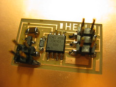
Hello board milled with 3 outlines and dasa board milled with -1 outlines.

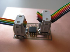
Connecting the plugs to the boards.


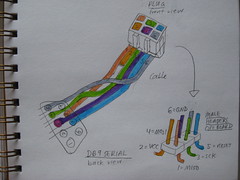
Sketches to help me think about the connections.

Before milling my boards on the machine, the first thing I wanted to try was to re-draw the hello world baord by hand with pens on paper. To be able to do this I started by tracing the shapes of the components to size so that they would be printed out for reference when hand-drawing.

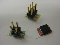
Realising that they were a bit small to draw with and also did not indicate what was supposed to be connected to what, I scaled them up and colour-coded the connections.
Finding an alternative circuit design, that did not require any paths to cross, proved harder than I expected. The final circuit still required two jumper cables for VCC and GND.

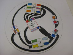
I coloured the final circuit black, took a photo of it, used Photoshop to increase the contrast and then placed it into illustrator and then created paths by selecting from the menu: Object --> Live Trace --> Make and Expand. This traced all the outlines for me. Then I simplified the paths by slecting from the menu: Objects --> Paths --> Simplify. I added text and used the Craft ROBO vinylcutter to produce the circuit.


Using masking tape to transfer it onto a piece of transparent plastic.


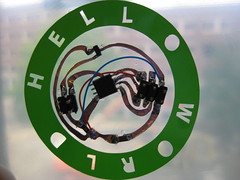
The heat from soldering the componetns warped the plastic quite a bit. When I first tried to upload the program to the board it did not work and then I noticed that I had missed one connection in my colour-coding. I added this connection with extra jumper wires, but still have not been able to program the chip.


Text cut from vinyl.

This is the Illustrator file with the vector version of the hello world original circuit as well as the components representations scaled to size.
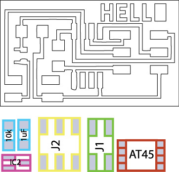
>> Download AI file of stencils