Final Project
Improvements on existing CNC Machine
14 Dec
UPDATES:
Getting there!
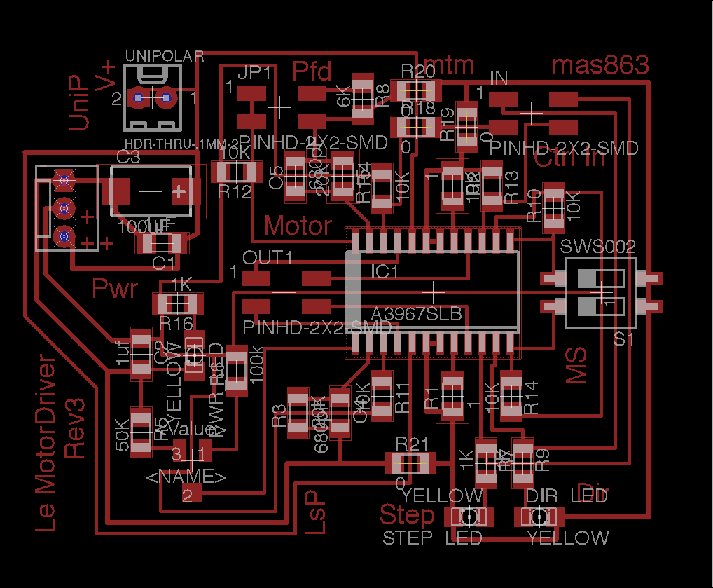
As of now we have X & Z working unipolar. Refer to Natan Linder's page for more details. We had Y going but now it is stuck. We've had remarkable trouble with the motor driver boards shorting. Natan and I both built them using solder paste and the reflow machine and two of the boards had problems with shorts. Maybe we used too much slightly stale solder paste?
Both boards have been re-built but aren't necessarily good boards.
Another lesson- DON'T BUILD YOUR OWN MOLEX CABLES. This may well be why Y is not working. Despite having the Molex crip and making what look like good cables, they tend to short. And being small crimps, they are a pain to make.
The goods:
|
|
|
9 Dec
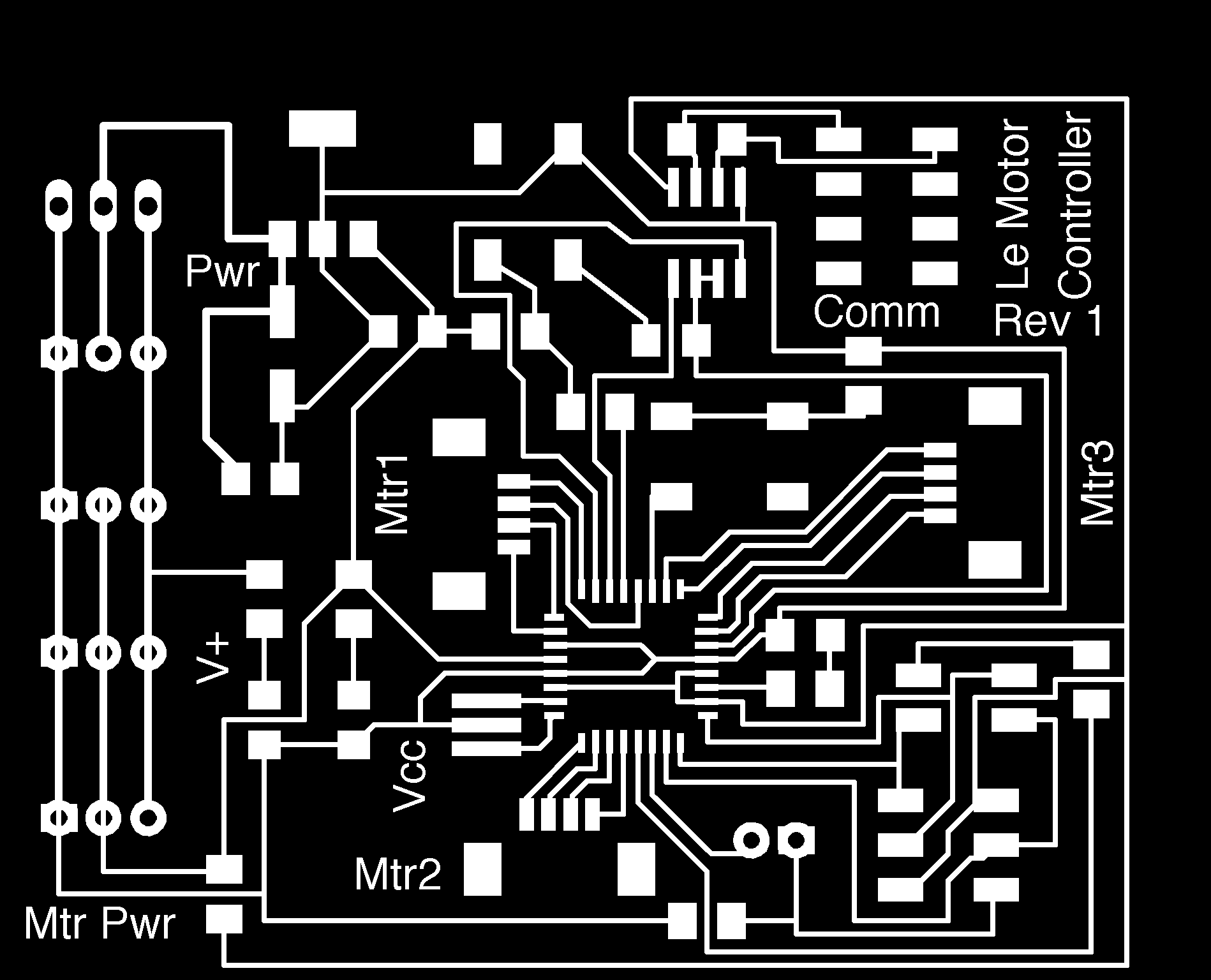
Progress! This morning I milled the first bipolar motor controller board. It is now built although not yet tested beyond power. It has a power in connector, main control inputs connector for direction, step, enable, and reset, and of course the output jack. I managed it with only 4 zero ohm resistors and it just fits on the small boards. A dip switch lets you manually set the step size and there is a jumper to change the PFD (percentage fast delay). The design is partly based on the SparkFun EasyDriver.
Assuming it passes functionality tests, this is largely the final version although I bought some alternative connectors in an effort to strengthen and limit the connection. They haven't come in yet. When they do, I'll do the next rev and start making a bunch of these. (Or at least the three for a machine).
Bipolar Motor Controller in Eagle
In the meantime, Natan has been rocking with the new frame design. He gave me a tutorial in Solid Works and I helped redesign the spindle head yesterday. He's just completed the first version. It is nice. Tight fit.
We opted to make the first machine Unipolar. Time to make a brute force board for that one.
Woot!
7 Dec
Last week I joined forces with Natan Linder. We've got fairly complimentary skill sets and can hopefully come up with something better by targeting different parts. Natan has been redesigning the bed for larger travel in all directions and we are working towards a modular head system. This past week was spent on project definition, meeting with others working on MTM, design and parts selection.
Personal Targets (in Priority Order):
Revised Motor Controller for bipolar motors:
Status: This has been researched, parts are mostly already bought with a few on order. Each motor will be driven by a separate Allegro motor controller driver connected to a master. The new mark up is in presently being done in Eagle with the target of being able to mill one on Tues. Once the individual controllers are complete I will build a control board based on the Atmega 88. Ilan is working on control systems that can run on this.
Internet 0 Made Machine Friendly:
Status: Right now internet 0 is either complexly coded or handles a full packet at a time. This is a problem because the present internet 0 implementation does not allow the chip to switch between internet 0 processes and the motor control processes which are time sensitive. My first intention is to see if I can effectively change Neil's present internet 0 code to be interrupt driven allowing the processor to switch between processes. If that appears too difficult, a back-up option is to dedicate one processor to handling internet data and communicating that data to the motor control systems. At this point I have fabricated the present internet 0 boards and am still familiarizing myself with the code.
3. MTM Visual System:
Status: Right now I have located a relatively cheap ($15) CMOS VGA camera and have actually managed to get data sheets (who knew how hard that was?). There are two purposes for this, one is to mount it to the head for auto-registration purposes (this could for instance increase accuracy for two sided milling). The second is the idea of building a camera head to photograph an object, take the outline, switch heads and mill away!
Schedule:
Dec 1 (Tues) : Initial design sketch and identification of any special parts required- Round One completed.
Dec 2 (Wed) : Parts Order placed- Round One completed
Dec 7 (Mon) : Physical parts cut and assembled (Natan's version first)
Dec 7 (Mon) : Motor Control Circuit Schematics complete
Dec 8 (Tues) : Motor Control Circuits Built
Dec 9 (Wed) : Runs as Present- Test Bipolar Motor Controls
Dec 10 (Thurs) : Interrupt coding.
Dec 10 (Thurs): Familiarization with Camera and sufficient design for parts sourcing.
Dec 12 (Sat): Round two of machine
Dec 14 (Mon) : Demo!
The majority of parts have been ordered. I am now on rev. 2 of parts requirements but have almost all the most key parts.
30 Nov 2009
Final Project:
I still intend to build my electronic hurdy-gurdy. But I'm too much of a perfectionist that it will either explode and be difficult to complete in time, or I won't be happy with it. Even though it incorporates much of what we have covered over the term, it is dubiously bounded for the time available. Which is great because I also really want to build a CNC. The plan is to take Jonathan's existing CNC design and enhance it in three ways:
Scale it in size on all axis.
Enable networked motor control.
Enable auto alignment and registration.
Full Description:
Scaled- I would like to be able to mill larger objects and mill wax slightly deeper than the present 1”. Plans are to essentially double all dimensions. This will provide an x-y surface roughly the size of the Modella. Due to bit length, scaling above the present z height is of limited benefit. Hard edges still won't be possible deeper than just over 1”. However it will enable soft edges where the sides are sloped. Scaling will require either thicker material or a change to a more rigid material.
Networked Motor Control- This will enable control of the machine from any computer, not just the one it is running on. Remote jobs may not be that practical, but being able to use your own laptop and not transfer data all the time is. This will require adding a network component to the existing control circuits and then adapting the control software to be internet friendly.
Auto-registration and Alignment- There are a couple benefits to this. First, it would simply be nice to have the machine automatically determine where the x-y origin are. Additionally, it provides confidence that stopped jobs can be restarted whenever. Even nicer would be if it was possible to be able to stop a job, take off an object, put it back and restart, or run a different job on the same object with confidence that the overlay will remain the same. The second aspect may be more difficult but would definitely be handy if I can complete it. This will require adding a CMOS camera to the present circuitry and then doing the programming for it to find and register an object.
Proposed Schedule:
Dec 1 (Tues) : Initial design sketch and identification of any special parts required.
Dec 2 (Wed) : Parts Order placed.
Dec 5 (Sat) : Physical parts cut and assembled
Dec 6 (Sun) : Circuit Schematics complete
Dec 8 (Tues) : Circuits Built
Dec 9 (Wed) : Runs as Present
Dec 11(Fri) : Program Motor Control
Dec 13 (Sun) : Program Auto-Registration
Dec 14 (Mon) : Last minute fixes!