Sensors-FSR Drum Pad
2 Nov, 2009
Project 7: Inputs & Sensors
Force Sensitive MIDI Control
The Project:
I targeted to make a MIDI interface object that triggers a note on when struck which has a volume tied to the force it is hit with. For the sensor I built a force sensitive resistor. The input goes through a voltage divider so that changes in resistance can be measured using the analog digital converter on the AT Tiny 44. The processor continuously polls the ADC to see if the voltage has changed. If it has changed it sends out a MIDI note. When the strike is over, it detects the return to normal resistance and sends the MIDI note off. Or that is one version of the code.
A Simple Force Sensitive Resistor:
Because I want an impulse pad sort of like a drum pad, I built a large force sensitive resistor (FSR). One typical FSR designs are to take two conductors and place a mesh between the two that separates them. When force is supplied, contacts occur between the conductors through the mesh changing the resistance of the sensor. I initially tried this method but was having trouble finding an effective mesh that would compress allowing contact between the conductors and also had the holes for those contacts to occur.
Another option is to use velostat as the separating material. Velostat is mildly conductive and its resistance will change depending on its compression. Thankfully Hannah had velostat and gave me some. I used two sheets of wire mesh separated by two sheets of velostat wrapped in non-conductive rubber to build the sensor. It is conveniently sized and has a touch of soft bounce to it. Yay.
The Board:
I built my own custom board. I needed to include the MIDI output and build a voltage divider. I included space for a capacitor across the FSR in the event I needed to de-bounce the circuit somewhat. So far it looks like the debounce is not necessary. I also included the circuit for a step impulse sensor. I did this because it can be easily configured as a second voltage divider to read a second FSR or I can use a step function to detect capacitance changes. This allows me to use the same board for proof of concept for either a multi-note interface or two typed interface. I'm presently involved in building a MIDI gamelan where we are looking to mimic the traditional playing interface. This involves a strike and a damp and this board will let me try out a couple different possibilities.
The board was done using cad.py. I found this very time consuming. It worked but seemed overly arduous for some simple things. I also added a MIDI out map and added pins for a surface mount npn transistor. Luckly I found the spacing on the transistor pins to match the width of the tiny44 pins so I could steal those as a template. I also kept the serial out for debug purposes. It has been definitely useful. Sadly, I forgot to add an LED or reset button. Both are musts for the future.
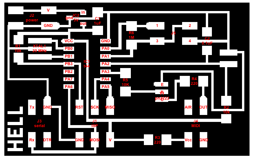
Voltage Divider, Step, and MIDI Out board
Milling and construction of the board went smoothly. I haven't added the debounce capacitor or the Step parts as I don't yet need them and once the header is in, it will be more difficult to change out any resistors.
Embedded program- Adc control in c:
Rather than adapting existing Assembly code, I opted to write my board's code in C. This isn't because I dislike Assembly. I actually like it. And I write my C code with the generated Assembly in mind. But I wanted to do some generic abstractions so that the setup can be easily switched. For this, C is better. An interesting note is that I also was figuring it would make processing easier. At one point I wrote a generic output function that would handle both serial and MIDI depending on how it was called. This demonstrated the problems with C compilers when a couple simple variable substitutions scaled my code up by a factor of 10. It should have made a difference of maybe 4 lines of assembly code. This code was also too large to fit on the chip. I had to break it up and not use as much abstraction. I got back to a good code size immediately, but I did find it a very prime example of inefficiencies in C compilers.
Again, I've written code that provides a lot of easy #defines so that configuring the ADC is pretty intuitive and straight forward and can be done without knowledge of the bits and significant knowledge of the registers. Another benefit of this is that if I change chips, I can use the same code once I've updated the #defines if it has a new register set.
I downloaded and used Cross-Pack to compile code successfully.
Included here is a somewhat messy set of code. You can also find the corresponding makefile in the directory: ADC Control in C
Working with MIDI Out- Oops:
Rather than a visualization, my intent was to use the MIDI out to control MIDI note events in a piece of music software such as Ableton or ProTools. However in order to do this I need a MIDI source into the computer. I think my board is good but I can't actually test it because it turns out none of my MIDI ins work. Oops.
Anyway, a couple notes on working with MIDI. I'll improve the write up once I've verified my MIDI works.
MIDI runs similar to serial with a few additional conventions. Firstly, the baud rate for MIDI is 31250. MIDI is also always a 3 bytes package of data for instance. The first byte starts with a high bit and the two subsequent start with low bits. This provides for basic synchronization. Note that there are only 7 bits for volume. If you look at the C code, you will see I and left aligning the ADC registers. This is because I am presently only reading the top 8 bits from the ADC conversion since I only have 7 bits of data space. This scaling could probably be much more intelligent. For signaling there may or may not need to be inversion. I can't remember if the signal static is high and then it drop to signal a one or not. My present C code has two options since I'm not sure which one is correct.
Useful site for MIDI programming information: MIDI Interface Construction
Verifying Everything But the MIDI:
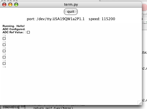
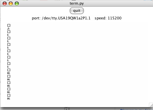
Thankfully I included the serial output on the board and that I can verify. I can't test the MIDI out since the baud rate is not standard to serial terminals. But I can make sure that my voltage divider is working and that data is sent as expected. Here are some fun screen shots. They are my not-very-exciting visualization.
Here my board says hello! It is running. At this point, I don't have the FSR hooked up so not much exciting going on in the output.
This time the FSR is connected. Look values! (There is extra padding which comes from the note-on instructions in MIDI)
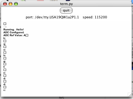
Push the pad and the values change!
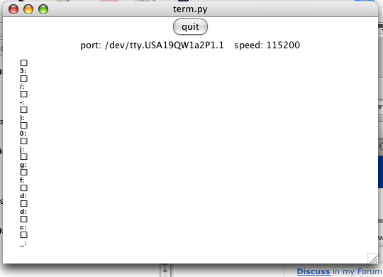
Don't push the pad and the values don't change (much). I wrote some simple noise handling code for verifying differences in amplitude should be interpreted as strikes.
Until I can read MIDI in, that's it!