 Microntroller Programming
Our assignment was as follows:
- read an AVR data sheet
- add a button to the serial echo hello-world board
- modify the serial echo assembly program to respond to the button
- modify the serial echo C program to respond to the button
AVR Data Sheet
Since we were working with the ATtiny44 this week, I decided to read the data sheet for that chip. It’s 229 pages long! And it’s very confusing. I’ve never worked with microcontrollers before, so this made me feel like I was drowning in a sea of bits and bytes without knowing which ones were helpful and which would turn my board into a pile of melted solder. At this point, it seemed almost helpless.
PCB Fabrication
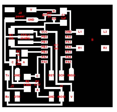
I was very excited to make another PCB since I enjoyed it so much the first time. When deciding whether to add the button in cad.py or remaking the board in Eagle, I realized that the button was already described in the board and I would just have to add it in the correct place and add the traces. While I’ll probably use Eagle in the future, cad.py seemed like a good quick method for the problem at hand. I ended up having to download gedit though because both notepad and wordpad messed up the .cad files when I tried to edit them. Good ole Microsoft…
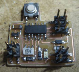
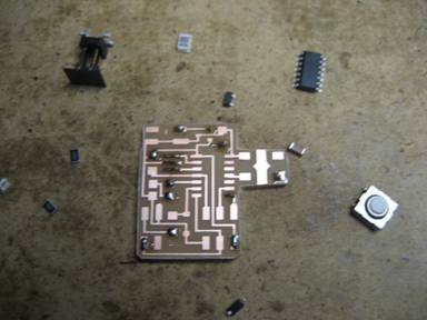
I then used the Modela this time (as opposed to Max and Ilan’s home brew machine from last time). The process was very streamlined and I was happy with how quickly I had my board. I then gathered all of the necessary components and went to work on stuffing my second board ever!
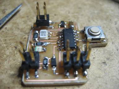
I was very happy with both how quickly I was able to stuff the board and at how relatively nice the solder joints came out. No re-work done here!
Programming
This was definitely the most difficult part of the assignment. I started working with the .asm file and first went through the existing file to understand how it used the instruction set and registers from the data sheet. After I felt like I had a handle on that I tried to implement my button as an interrupt. I spent a long time trying to figure out how to set the correct bits to allow the interrupt and by the time I finally figured that out I realized that I had no idea how to catch the interrupt to have the chip do what I wanted!
I searched through Google extensively, but apparently nobody writes in .asm! While searching I decided that I was going to scrap the interrupt attempt and make the pin a standard input. I ended up getting that to work, but because the program sits in the loop waiting to receive a character from the keyboard, the button press didn’t show a result unless I held the button down and pressed a key. While technically I completed the assignment because the button was doing something, I wasn’t happy with it. I was determined to get the interrupt method to work.
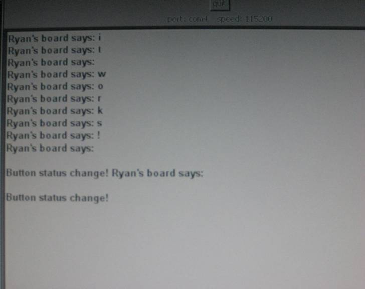
I did finally found a way to direct the interrupt I wanted (PCINT0) to do what I wanted it to do (blink the LED and print “Button status change!” on the screen). There isn’t anywhere in the data sheet where I could have found it, so I’m glad I found it randomly online. Anyway, once I got the .asm file to work I moved on to the .c file. Everything went smoothly until once again I had trouble figuring out how to direct the PCINT0 interrupt to do what I wanted. Luckily, AVR Libc makes this much easier. I got it to work and was amazed at how much larger the .hex file was using .c (1530 bytes) instead of .asm (661 bytes). I guess I can see why .asm is useful (grudgingly).
My code is here:
I used AVRStudio for my .asm programming and WINAvr for my .c programming.
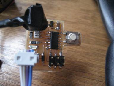
And it works!!!