To cut to the chase, here's the final product from this week:
This was a very educational, if not highly productive, week. I spent a lot of the week learning how to design circuits in Eagle-- which is not always the most intuitive piece of software.
I had originally wanted to use the accelerometer and so began work on integrating it into one of Neil's boards. First I had to find all the components in the various libraries floating around-- and figure out which components I was going to have to build myself. I couldn't find a library of the headers we use so I had to make a library of them. Then I had to figure out how to
integrate the accelerometer into the circuit and attach it to the microcontroller. The data sheets of each have relatively cryptic "instructions" on how to hook them up. One thing I'm learning through this class is that when it comes to electronics there basically isn't any one "convention" or "language." Everyone writes in their own dialect and it's up to the reader to decipher what it is their trying to say. After a long time of trying to figure out how to hook it all up, and getting less than straight answers from the various TAs, I decided to abort the accelerometer mission. I hope to come back to it for my final project, though.
I then moved onto the temperature board. With my newfound Eagle skills I decided to redesign the board a bit to get rid of the Rx connection and power it via a battery instead of from DTR. All I wanted the board to do was light up some LEDs when I breathed on it, so I wasn't going to need the Rx connection and I didn't want to have to be connected to the computer for power. Redesigning went pretty well (see "Eagle Tips for Beginners" below). I then cut it on the vinyl cutter and transferred it to a scrap piece of plastic. I stuffed the board and loaded Neil's temp code onto it and magically it worked!
Unfortunately this was really a false positive and I thin the LED only went on and off because i was pushing on the circuit and making a connection. I had only modified the code in one way-- simply to change the output pin to be the pin my LED was on.
I was so excited that it worked (and it was only Thursday!) that I decided to get fancier and try to run a few LEDs off of the one pin (I was using the Tiny45 and only had one pin left). I wanted to be able to breath on the circuit and have three petal LEDs light up. My circuit was a bit messy so I decided to re-cut and stuff the whole thing. Per Nadya's advice I also integrated a NMOSFET into it to run the multiple LEDs. (From my note earlier about the language: the MOSFET data sheet had three letters attached to the three pins to explain how they should be connected. They were G, S and D. You would think G would be ground, right? Nope. G= Gate= microcontroller pin. Ok, then it said S was "source". That would be power (voltage), right? Nope. That goes to ground. D was "drain" that would be ground, right? I think you get the point....)
I cut and stuffed the new board and made my little LED petals. But this time I was not so lucky. Nothing lit up when I loaded the code. Bummer. David Carr happened to be walking by so I snagged him and he generously helped me with the code. Together we wrote a C code to run just one LED, hardwired directly into the microcontroller pin. He helped A LOT and explained a lot about what the different registers mean. And in the end this was the result....
THANK YOU DAVID!!
I was so excited about this that I forged on to get all three LEDs working on the petals. After some troubles with bad connections I got them to light up, but quickly fried the 50 ohm resistor I had placed before the MOSFET. I replaced it with a 500 ohm resistor and voila! It works great. (see video at top of page)
Eagle Tips for Beginners:
1) If you can't find the component you want search the web for libraries. (Spark Fun has some good ones). Also, if you find one very similar to yours compare the footprint to see if you can just use the similar one.
2) On the Library window (when choosing components) the button DROP does NOT mean "drop the component onto your board." It DELETES the library and you'll have to go find it again.
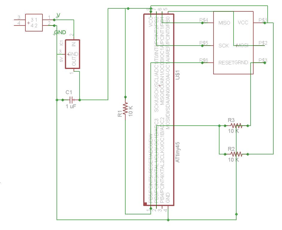
3) Place your components in the Schematic first and make connections between the necessary pins but don't worry about routing at this point. Lines can cross each other in the Schematic. (if you have a lot of connections see #7)
4) Place your components and make your schematic in a relatively coarse grid (.05 - .1 in) otherwise it's nearly impossible to make the connections.
5) When making a part in a library, make the package in a fine grid so it's exact, but then make the symbol big and in a coarse grid so it's easier to attach in the schematic.
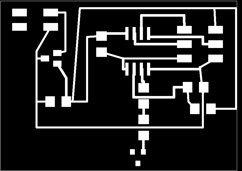
6) When exporting for cad.py:
a. Turn off all layers except for the red and outline layers
b. export as a MONOCHROME .png file.
7) A wonderful way to deal with too many wires in the schematic is to name and label wires. To do this:
make short wire segments coming out of the microcontroller pins you'll be using most
use the name command to name each of these wires
Then use the Lable command to show these names
Now when you want to connect a component pin to that wire just make a short wire segment from the pin and name it the same as the pin's name. You will be asked if you want to connect these nets-- say yes. You won't see a wire connecting them, but they are connected. Magic.
Here is the code I used to get the LED(s) to light. Basically it sends power to pin when it senses a voltage that's about half of the
VCC:
#include
#include
#define F_CPU 1000000UL // 1 MHz
#include
#define TRUE 1
#define FALSE 0
#define LED PB4
#define TEMP _BV(MUX1)|_BV(MUX0)
#define THRESHOLD 488
/*
* Do all the startup-time peripheral initializations.
*/