


Background
As a child, I always dreamed of having a Harley Davidson motorbike. This was destined to remain only a dream. When I grew up I swore that my child would not feel the anguish of wanting to own a motorcycle without the ability to fulfill his dream.
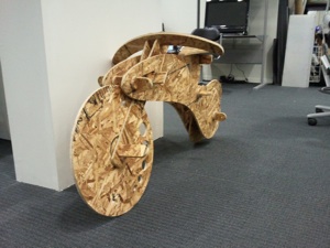
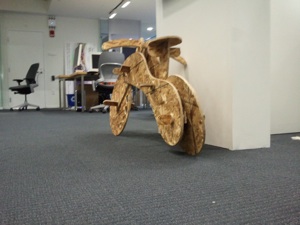
So I decided to manufacture a OSBike (Bike made from OSB), because I there is no way I would let a child of mine ride an actual motorbike.
Some tezxgt

Design
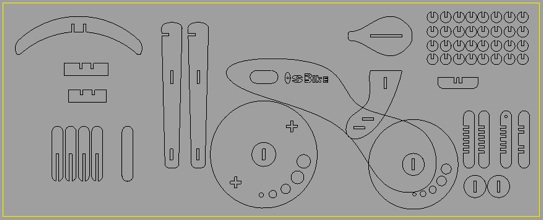
I used Rhino 4.0 to design the bike. Although this was he first time I used Rhino, I found it quite easy to migrate from Autocad (which I had used in my previous assignment). The tool is surprisingly intuitive yet very powerful. a variety of good tutorial can be found here .
The body of the bike was the most difficult shape to create. I wanted to create a sense of free flow. In order to achieve this I connected many curves to one another using the curve tool.
The fabrication process
I used OSB (Oriented Strand Board) to fabricate my bike. The process:
-
1.Create your design using your favorite modeling software
-
2.Export to .dxf file format
-
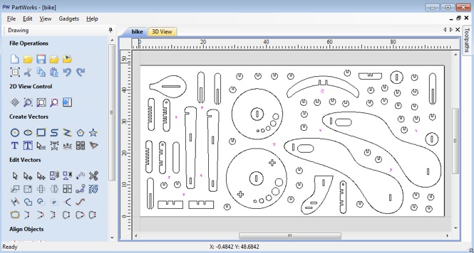
3.Import to PartWorks 2D
-
4.Create Drilling path - This path will be used to drill holes in “empty” spaces of the design. These will be used as mount points which will be screwed down to the sacrificial layer.
-
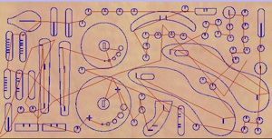
5.Create Profile Path (single or multiple) - In my design I had parts within parts (such as the center of the wheel which also served as an axis. In such a design it is important to define multiple paths. The first path is the internal parts that should be cut out first. If we start straight from the external profile, the parts may move and then we will not be able to cut our internal paths in an exact manner.
-
6.Save Paths
-
7.Open the ShopBot SW and open the paths that were saved.
-
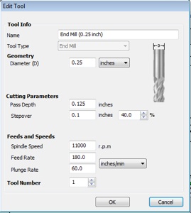
8.Mount the correct Bit onto the ShopBot (I used a 1/4 inch bit)
-
9.Make sure the sacrificial layer is clean and without sand dust from the previous job. This may cause your material not to lay evenly and the cuts will not be in an even depth
-
10.Lock in the X,Y Origin and the Z height using the Shop Bot Software
-
11.Switch on the Spindle (by inserting the Key into the Shopbot control Box). Make sure the emergency stop is released.
-
12.Switch on the Vacuum via a switch near the ShopBot control Box
-
13. Simulate part of the run, in order to make sure that the spindle stays within the limits of your material. This can be done by choosing Simulation mode in the ShopBot Software
-
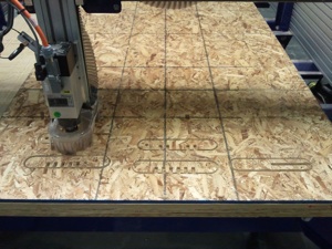
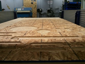
14.Execute the path

Construction of the Bike
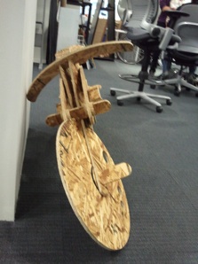
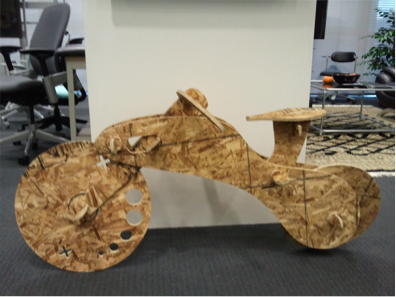
After retrieving all of the cut parts from the OSB plate it was time to construct the bike. I used a mallet to insert the pieces into place and the design came to life.
Conclusion
This was very fun project. I learned to respect but fear the Shop Bot. Although it is a deterministic machine, its inputs are varied - post processor of path file, location of material, speeds and depth of spindle, etc, etc.
This can result in unpredictable behavior. example - during one of the trails I didn’t notice that the post processor had changed from the default. When initiating a test cut, the shop started to move in an unplanned direction.
It is always best to run at slower speeds during the first few times you work with the bot, in order to get a true grasp of the process.