Input Devices - Extra Sensitive Microphone
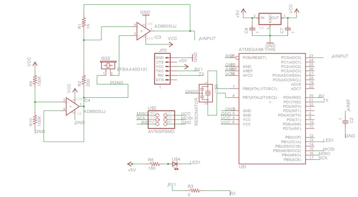
And So It Begins..... The Schematics
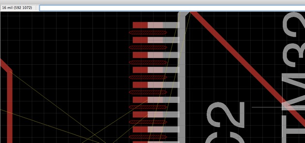
I decided to use a ST32M processor in order to utilize its larger flash memory, wider ADC and higher frequency. Unfortunately, After I had my schematics ready, I found that eagle did not like my design and the DRC failed. Apparently the width between the processor pins was less than 16 mils. As time as running out, I decided to abandon the ST processor for this week and go with an ATMega88.
My Conclusion - Eagle = Evil
The more I use eagle. the more I hate it. In order to connect nets to pins you must only place them on the very edge pin, otherwise - eagle does not understand that they are connected. In addition, when copying a component, it can not be connected straight away after pasting, but rather you need to past it, and then move it again for connecting to the relevant pin.
And lsat but not least - Eagle’s auto route is just horrible. I had to give eagle clues by using 0 ohm resistors in order to get it to route. I actually ended up finding the right placement for all the parts, so that eagle would agree to auto route, but this was a very painful process.
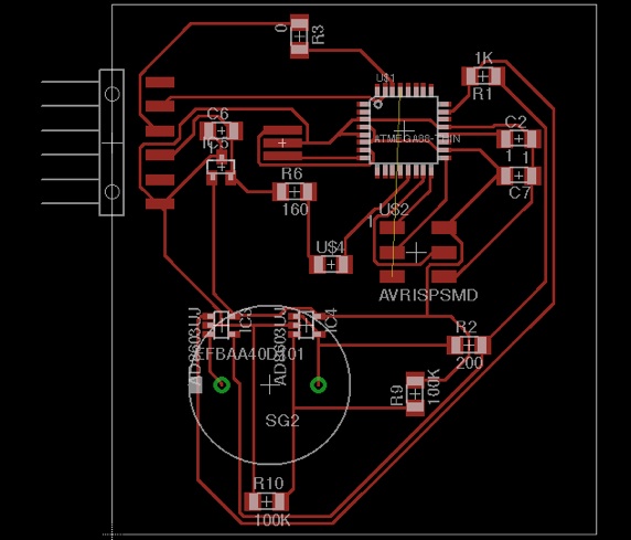
Yeah - I got it to route !!!!!
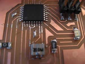
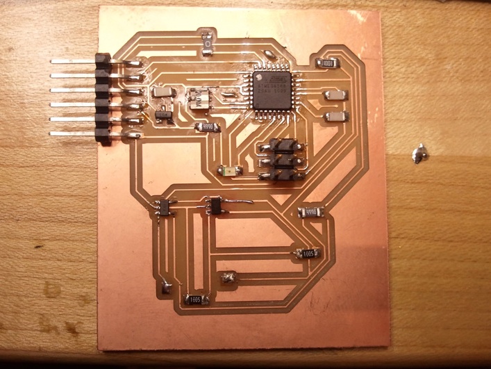
Milling the board
I had to to mill my board 4 times. since there were only small substrates, I found out during the milling that my design would not fit. After optimizing and rerouting I got a small enough design.
During the 2nd mill, the bit broke. I have no idea why - the board was leveled and the speed was 3. I guess it just one of those things that tend to happen.
3rd time - We used a 4 flute end mill. This produced a very jagged PCB, and the traces were easily ripped off.
4th time is charm - after finding another 2 flute end mill - I successfully milled my board (as can be seen below ).
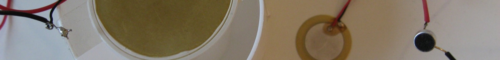
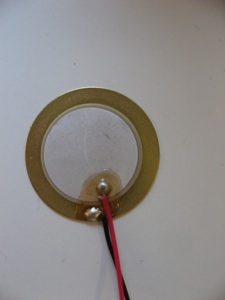
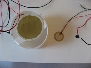
The Sensors
I tested with 2 sizes of piezo rings and the Electret microphone, I connected each one of them to the scope in order to test their response. It seems that the biggest Piezo ring had the best response and was the most sensitive so I decide to go with that. I “fabricated” a casing for the biggest ring in order to prevent it from breaking and to shield it from outside noise.
Shiny and Smooth !

60Hz is Evil
My circuit was being attacked by the dreaded 60Hz frequency (or 50).
This was probably due to my long unshielded wires. Next time, I will have to deal with insulation - or with adding a notch filter
Testing the sensitivity
After finding a location with minimal interference, I test the sensitivity of the sensor. Even light touches yield a very good response, so I believe that I can use this in my stethoscope design. Due to the interference, I could not actually probe for heart sound.
Testing the Gain
It seemed that my gain circuit was working. I connected a scope at the input of the piezo and found that it produced a level of a few hundred os mili-Volts. After probing my processor input, I found that the gain had increased voltage to around 3 Volts. Since my circuit was running at 5Volts and this was used as my analog reference as well, it meant I would be able to sample the signal with enough resolution.