.: week 10.output devices :.
musiPresence
My idea this week was to create a device with a servo, LED, and speaker that would give output based on the movement of an accelerometer - more specifically my project from the input devices week. The idea is that this device could be in one location and be an expressive outlet while a musician would perform in another location. I wanted the servo to move with the position of a cello bow, the LED to light up based on the speed of bowing, and the speaker to output a frequency corresponding to bow position. I didn't quite get there, but I made some progress.
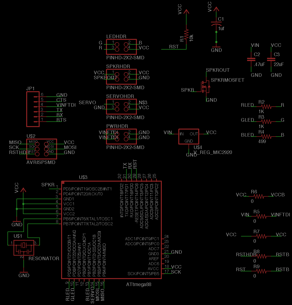
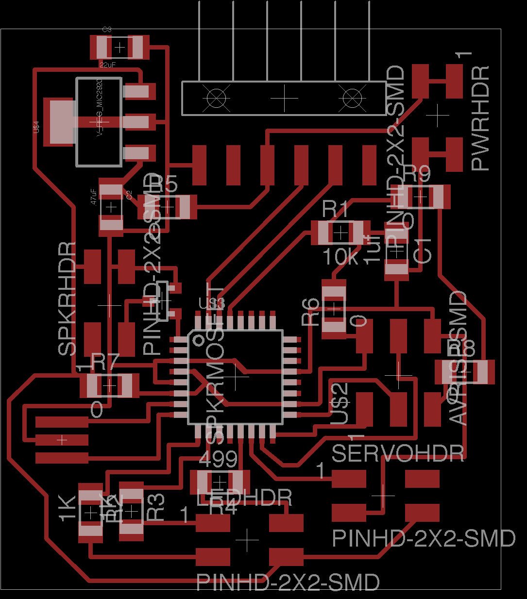
Board design
The board design and routing was much smoother this time than normally. I stepped up to an ATmega168 for this week, and I absolutely love it. Plentiful pins and a plethora of program memory definitely justified my step up to the ATmega.
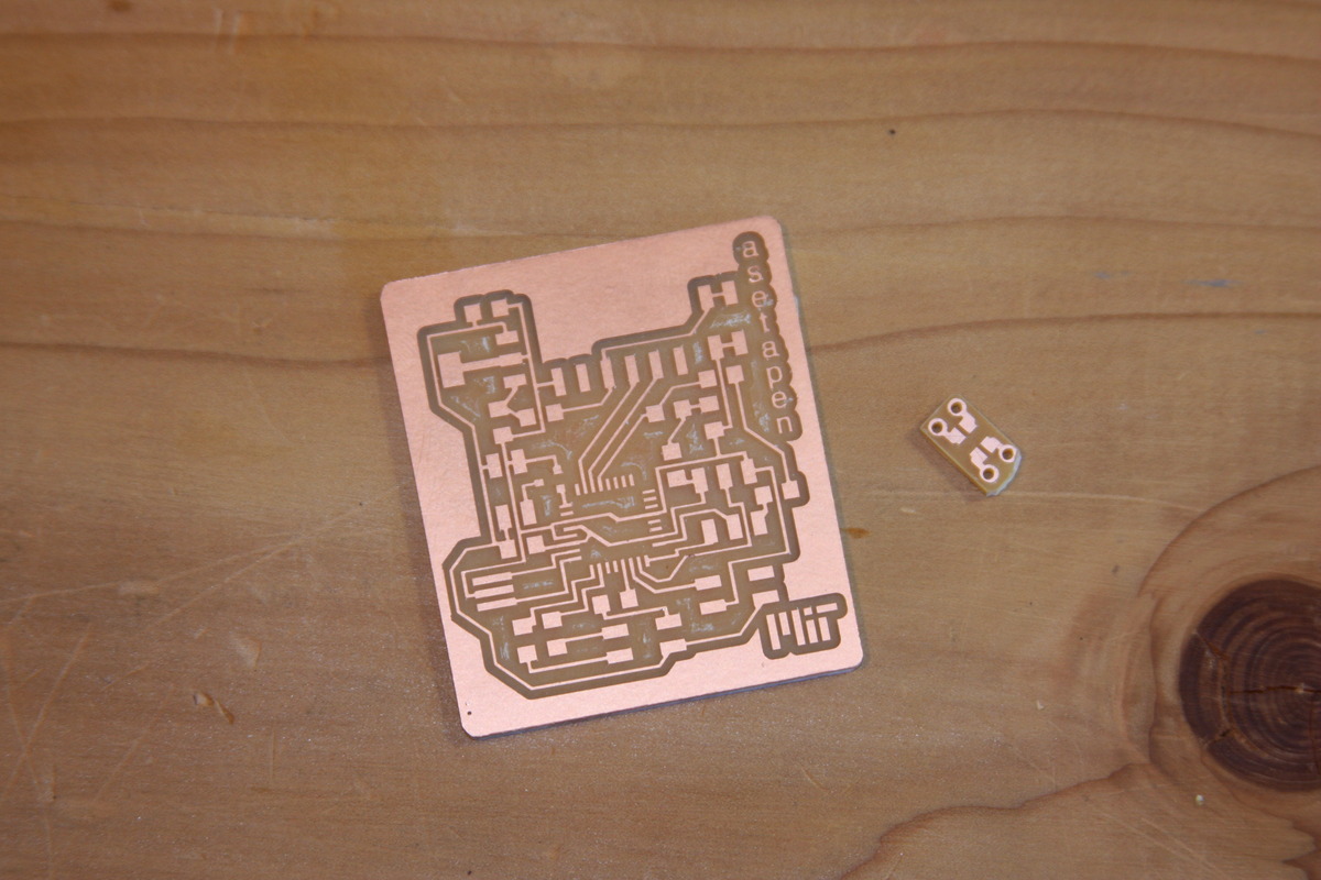
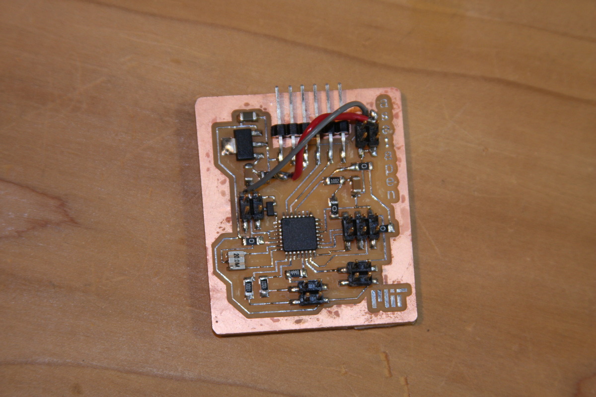
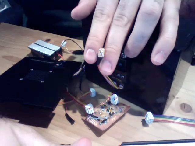
Milled / Stuffed board:
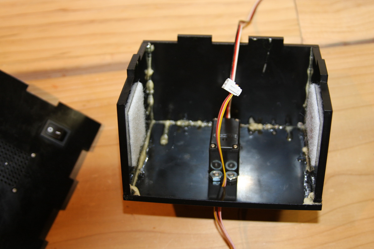
Enclosure
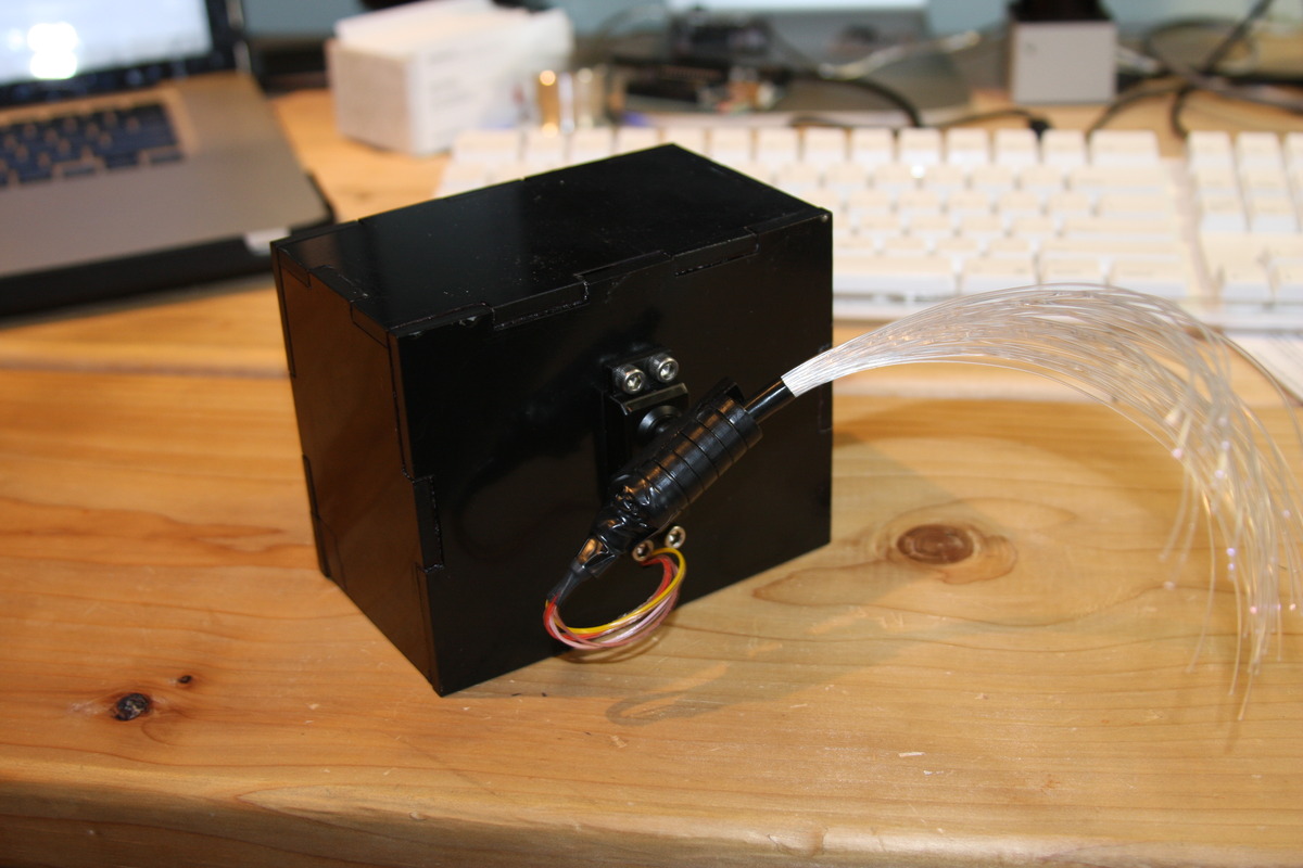
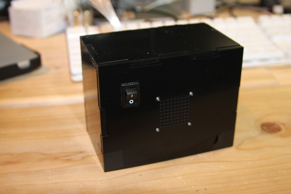
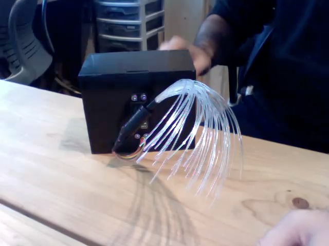
I laser cut an enclosure out of black Delrin. The Delrin seems to have a much lower melting point than the acrylic I'm used to, so the press-fit didn't work particularly well, but a little Gorilla glue saved the day. I also cut a speaker grill, a slot for a power switch, and a mounting bracket for attaching a bundle of fiber-optic cables to the servo arm.
Gluing the enclosure together:
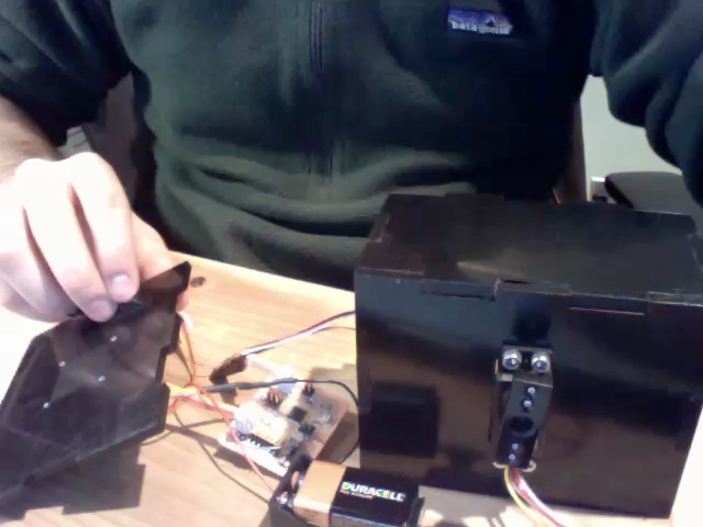
Finished enclosure:
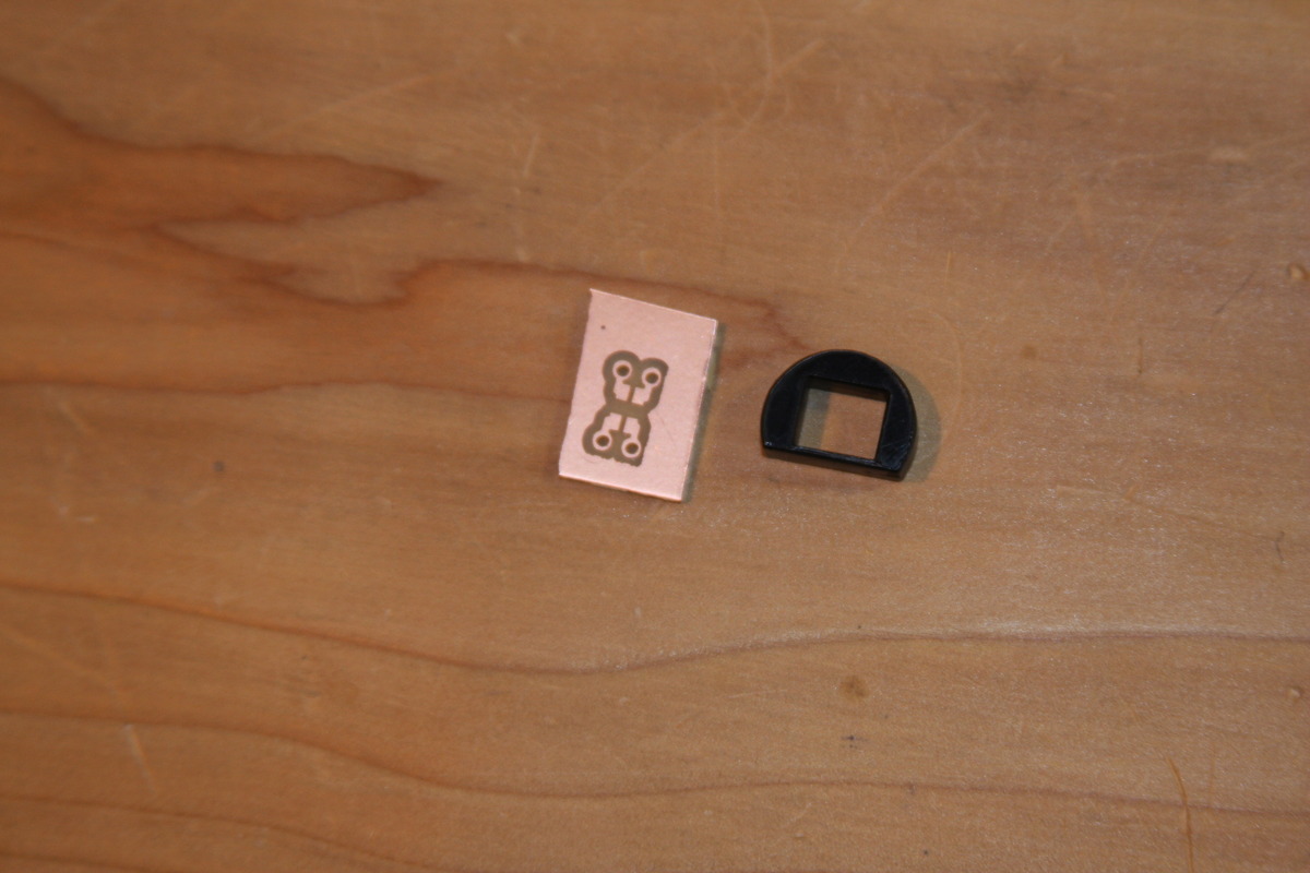
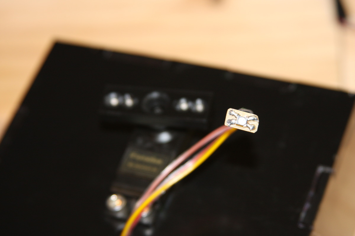
RGB LED
I was able to control the RGB LED using the hardware PWM and a signal generated in software. The biggest snafu was that the datasheet for this RGB LED switched up the pins for the common anode and the green cathode. It seems as if, this time, the "read the datasheet" mantra wasn't too helpful.
Servo
I had a spare servo laying around, and I definitely learned a lot about PWM from getting this servo running. Now I can use an oscilloscope! Lesson #1 for servos (and probably most other components): READ THE DATA SHEET.
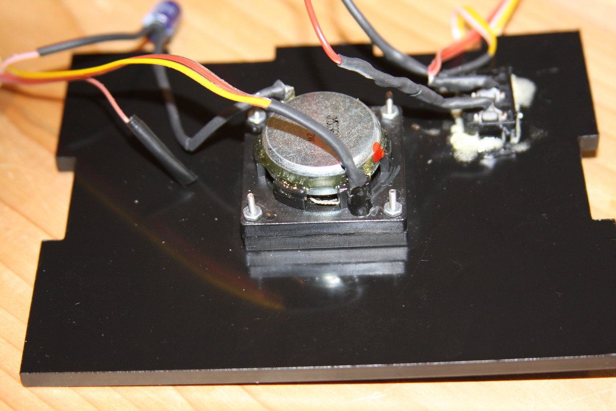
Speaker
Unfortunately, the speaker was too quiet to be heard (unless you press your ear right against the speaker grill). I followed Neil's speaker example exactly, but the power was never enough to get the frequencies to be clearly audible. I experimented quite a bit with changing the current difference, the PWM modes, and the PWM frequencies. I also added a 100uF capacitor between the speaker and the MOSFET, which kept the speaker from getting very hot when powered.
Problems
After getting my accelerometer communicating wirelessly using the XBee protocol and writing a nice filter that cleaned up the data, I had a strange problem that the PWM signals from my board were wonky when an FTDI cable was attached. I didn't have time to get to the root of the problem, but I'm very close to having the accelerometer wirelessly control the servo and LED.