.: week 8.input devices :.
Sensor-outfitted cello bow
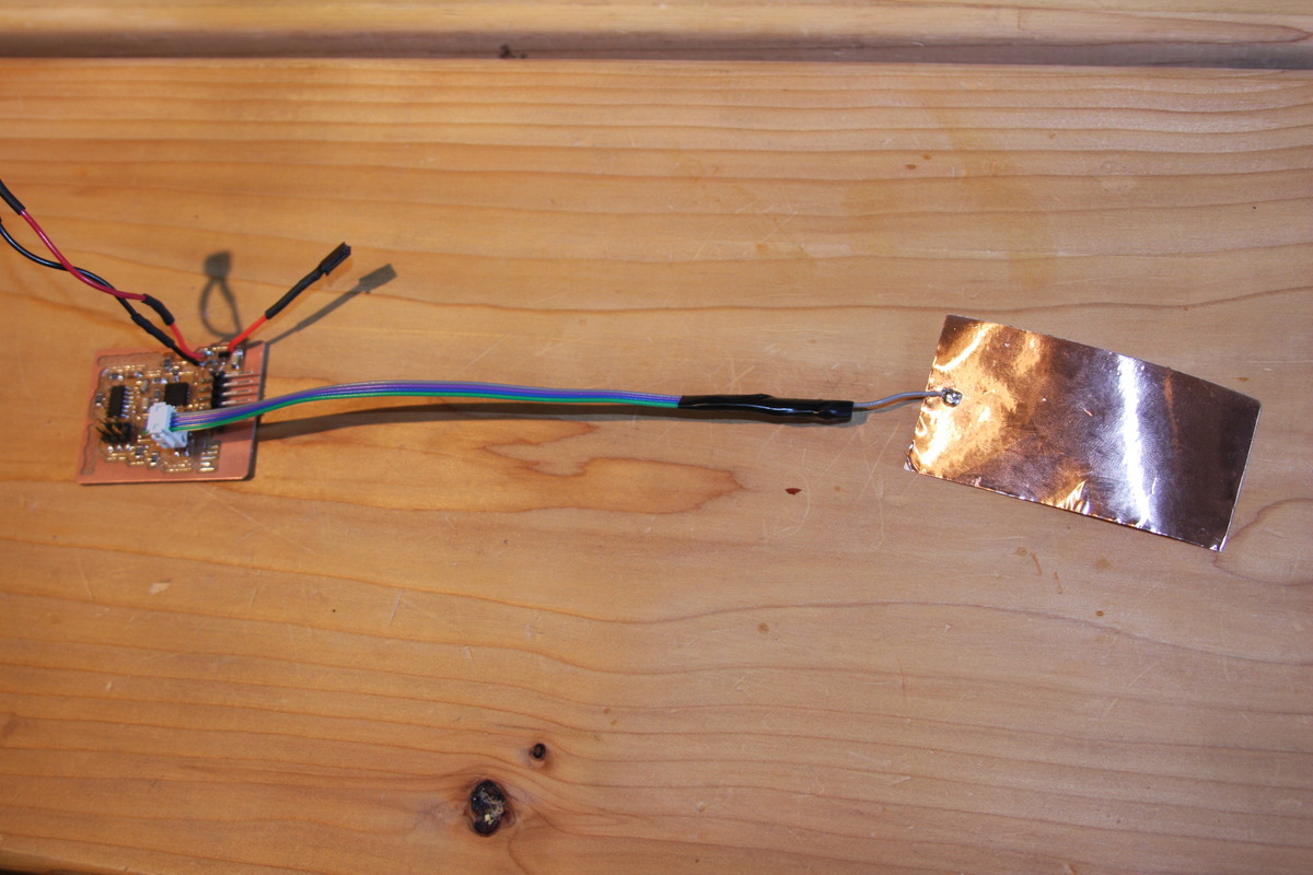
This week, I set out to fab a snap-on assembly for a cello bow that contains a board with a 3-axis accelerometer for sensing bow movements and a capacitive sensor that can detect when a person is holding the bow. Here is my journey towards this goal.
Design
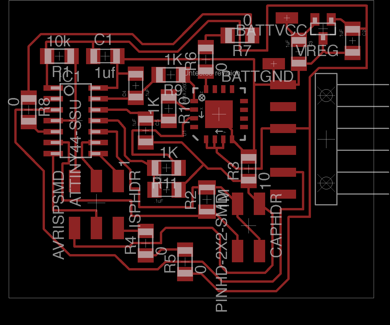
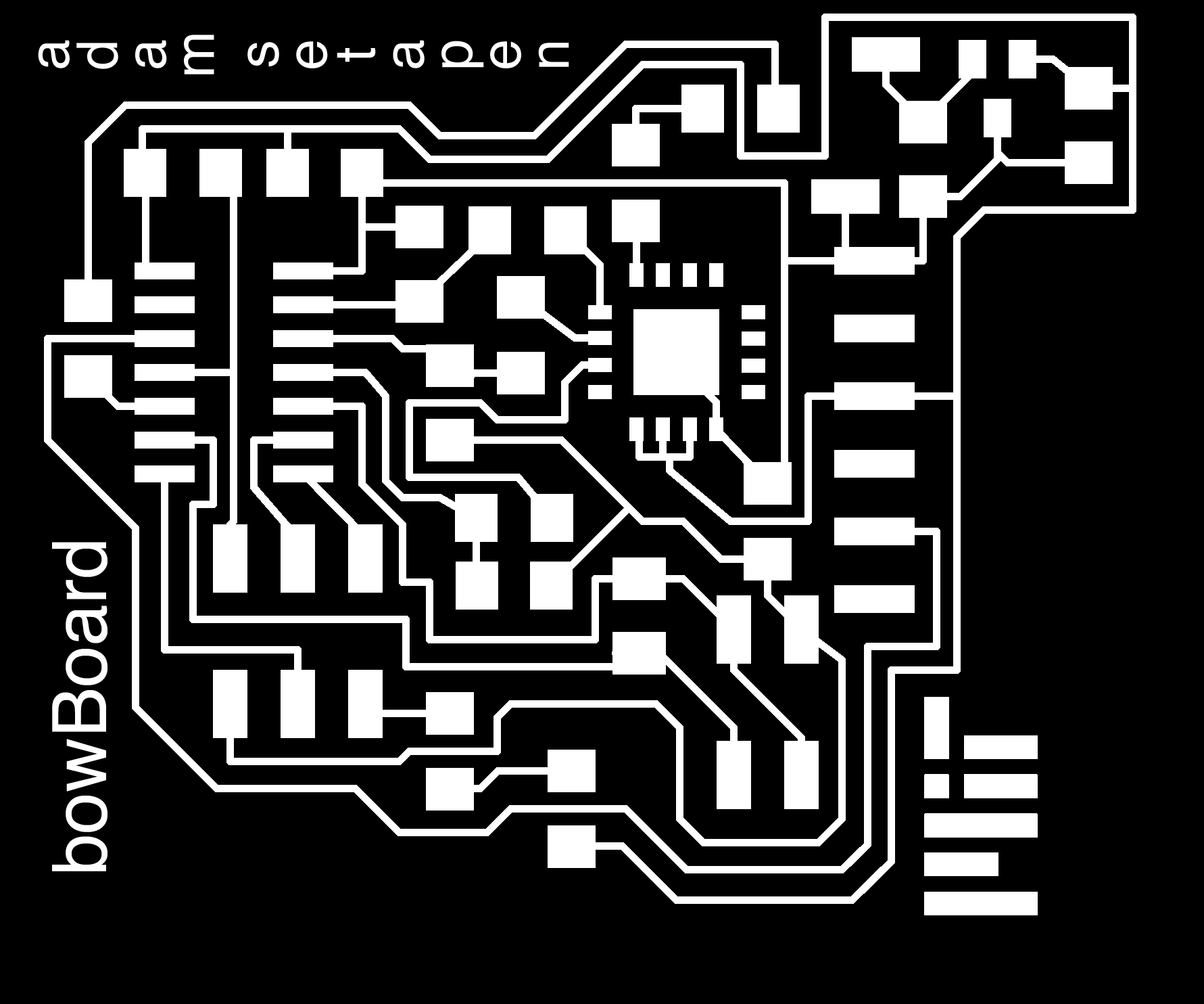
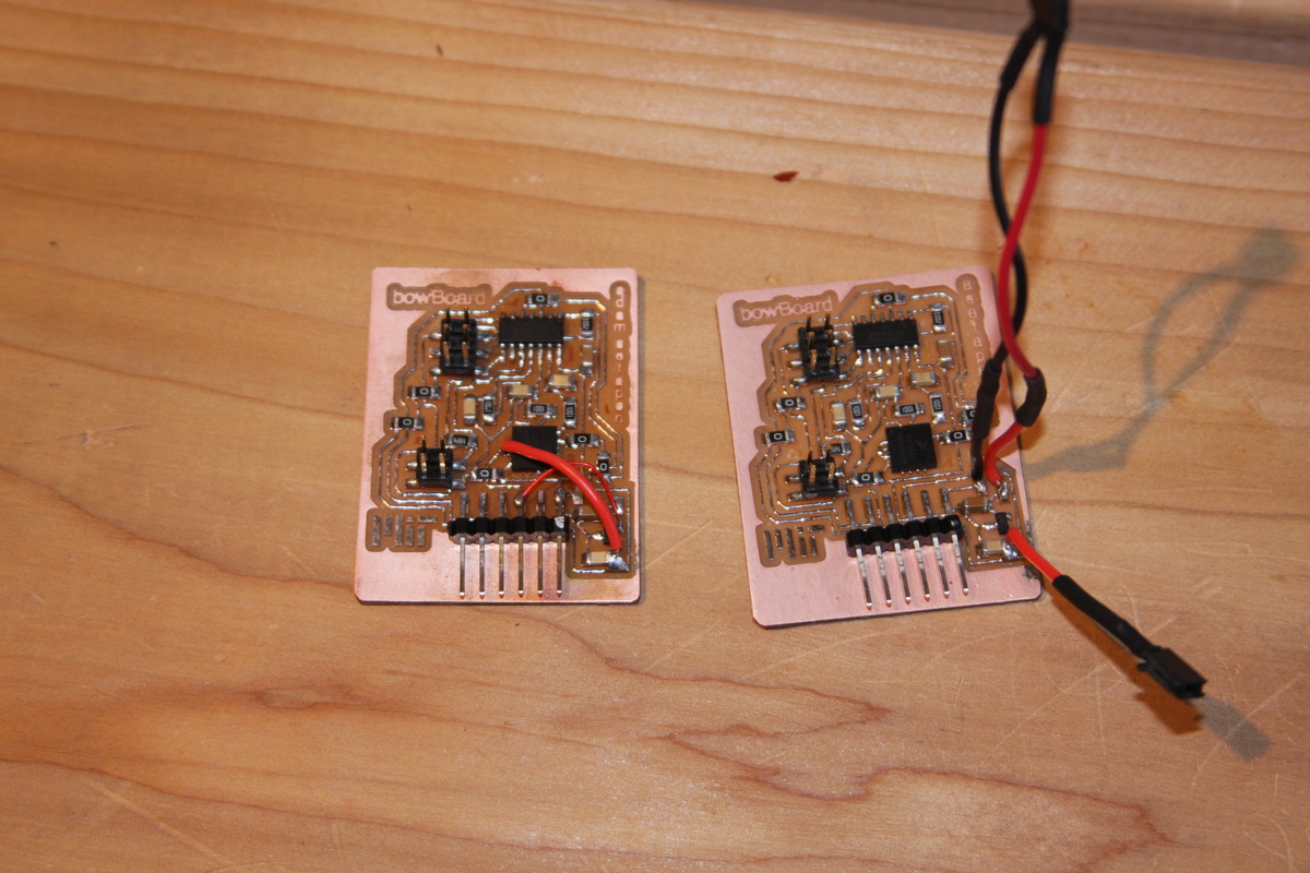
I laid out my board in Eagle, and I had a MUCH easier time this week with the PCB design and routing than during the week on microcontroller programming. I still had to use a bunch of 0 ohm resistors, but I managed to make a fairly compact board:
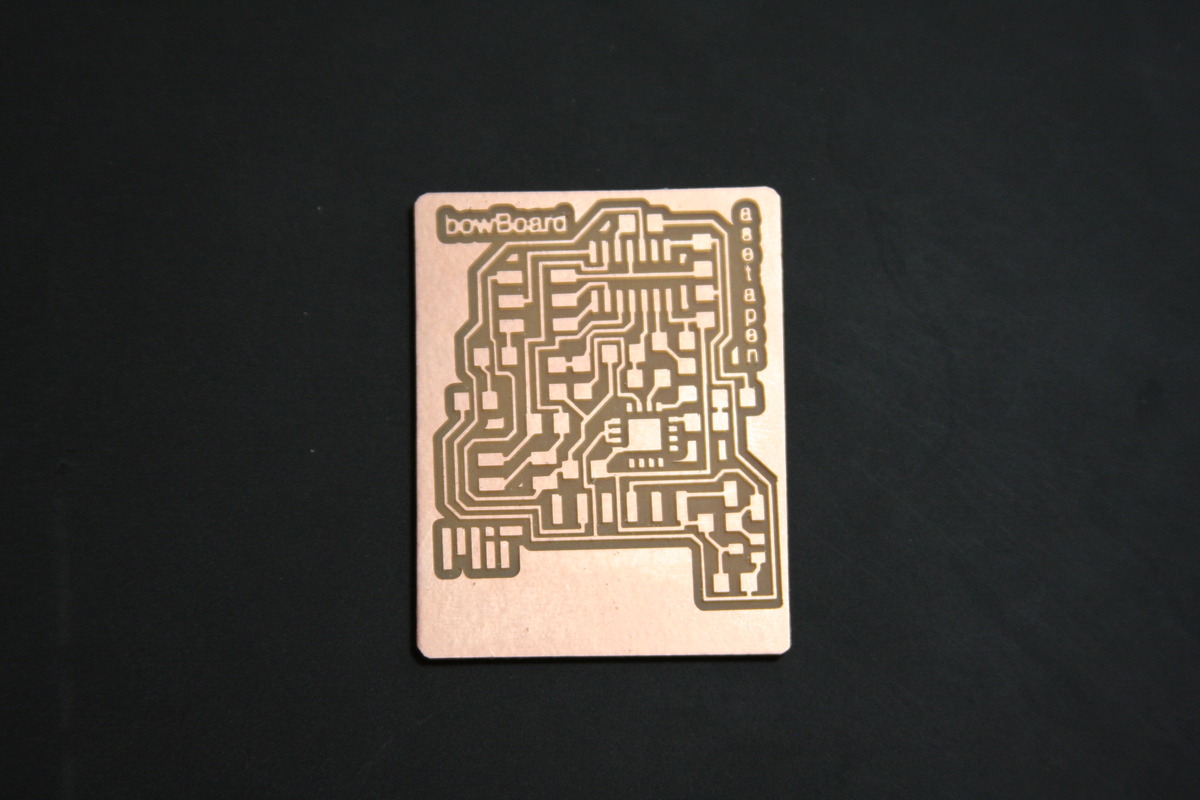
After milling with the Modela
Capacitive Sensor
I modeled my capacitive sensor after Neil's example - simply using a step-response. However, I did the analysis of the step-response on the ATtiny44. This proved to be slightly challenging along with the rest of my code - fitting everything into the program memory was quite difficult. I connected a copper sheet to the sensing pin for the capacitive sensor, and it works quite well.
Accelerometer
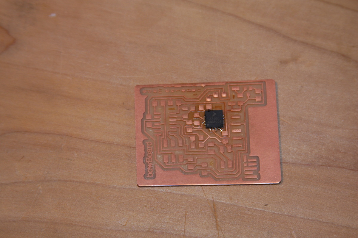
I used a Freescale MMA2760Q 3-axis accelerometer, set to have +6g sensitivity. This chip was a QFN package, so I had to learn how to use solder paste and a reflow station. SUPER-SPECIAL-THANKS to Brian Mayton for helping me out with this.
After reflowing the accelerometer to the board:
I stuffed the rest of the board, and everything went according to plan...
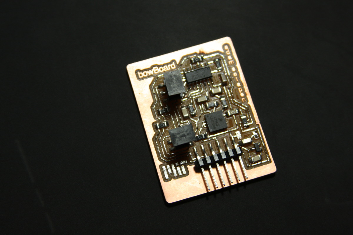
...until...
...I plugged it in. First, I thought (incorrectly) that the FTDI cable supplied 3.3V, but it turns out it supplies 5V over VCC - just uses 3.3V for communication. So I fried an accelerometer that was rated for 3.3V. Also, I fried a 3.3V voltage regulator that was being fed 5V to the output pin. Lesson: triple check ALL voltages, and know how much every component supplies / is rated for.
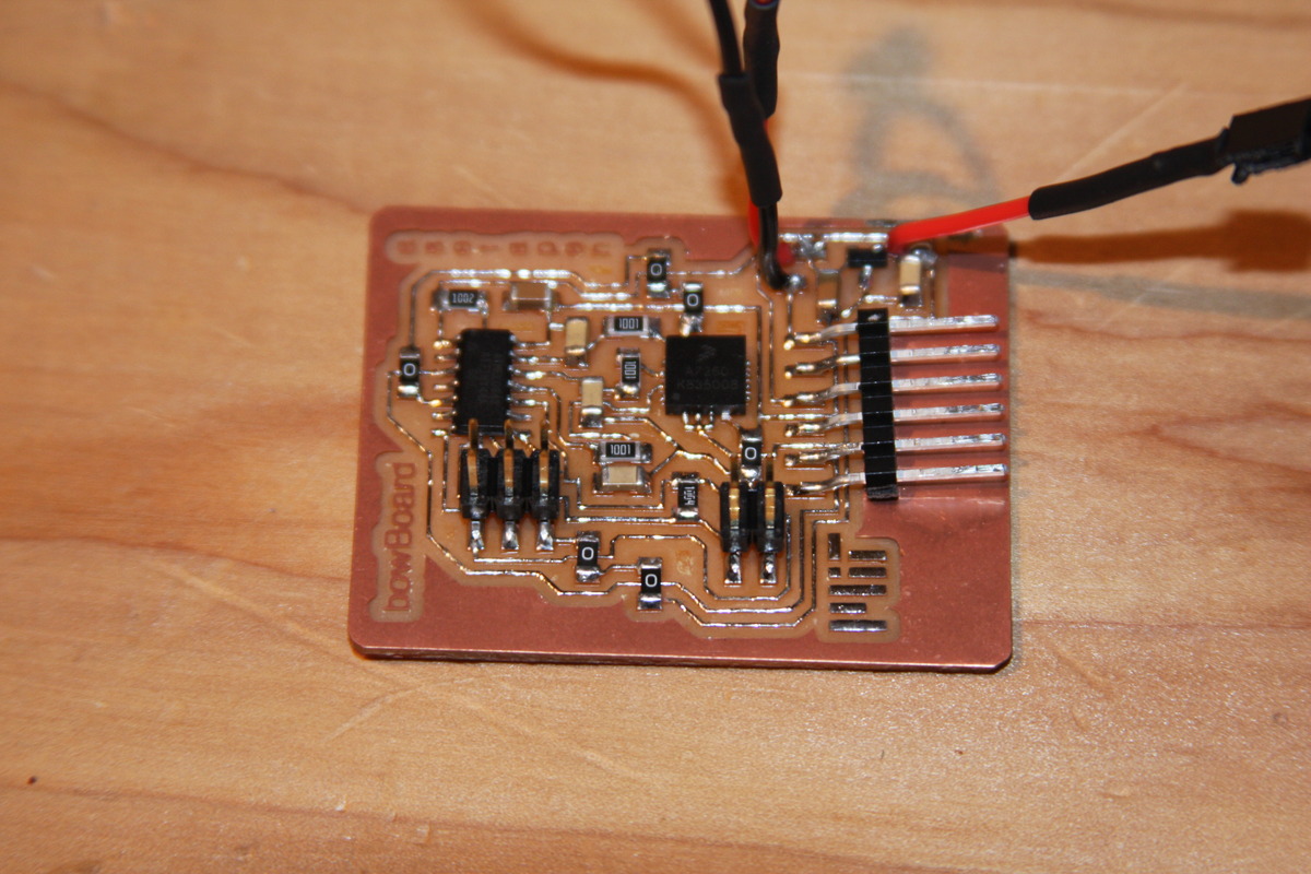
I ripped up the accelerometer and put a new one on. I had to rip up and wire a few traces together to fix my voltage problems. After debugging for a bit, I plugged in my FTDI cable and the header pins ripped up a bunch of the traces and pads. So I had to make another board:
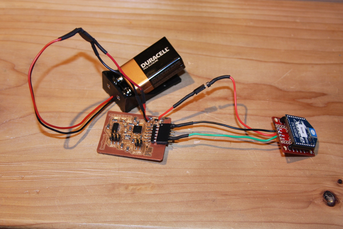
After some serial debugging (which was resolved by the F_CPU being set for no external clock), I got the board working. The board is powered by a 9V battery and communicates wirelessly using the XBee protocol/hardware. I'm excited about implementing my own communication hardware/protocol in a few weeks. The final wireless board:
3D Printing, Take 2
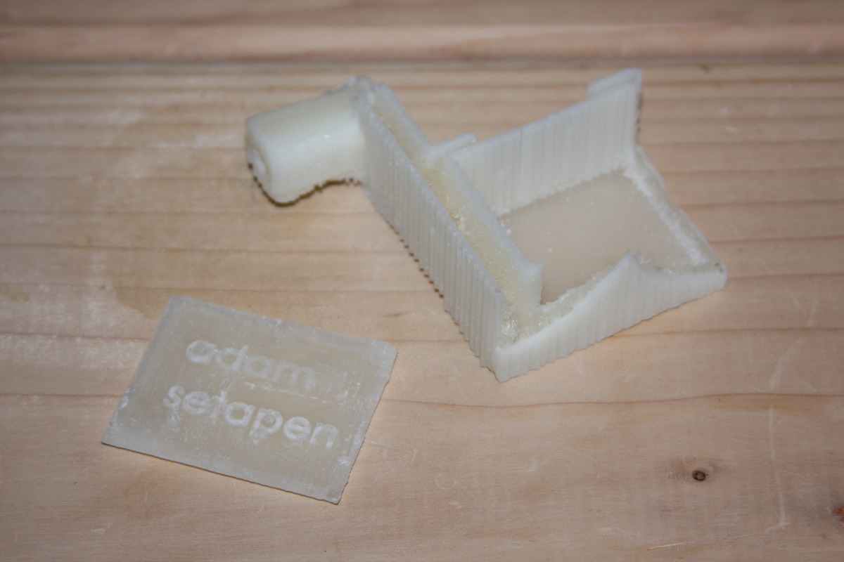
I tried to 3D print a snap-on case that would house the boards/battery, but something went terribly wrong with the Invision printer. The bottom layers printed fine, but everything else only printed the wax support - the structure was just "goo". After checking my STL file with John and Tom, we decided to print it again - this time on the Dimension. Here are the results of the first botched print:
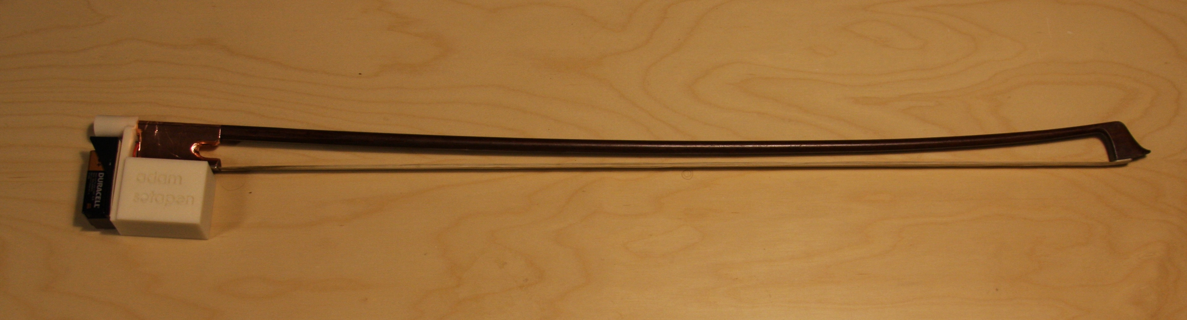
The second print worked out much better, and my measurements of the board worked perfectly. My accelerometer and capacitive sensor now are housed inside a slide-on case for a cello bow, which communicate wirelessly and are powered by a 9V battery.
Piezo Investigation
I looked into four different piezo sensors for sensing the sound of a cello:
I hooked them up to a little preamp with a JFET that I purchased parts for and stuffed. The sound wasn't great through an 8 ohm 5W speaker.
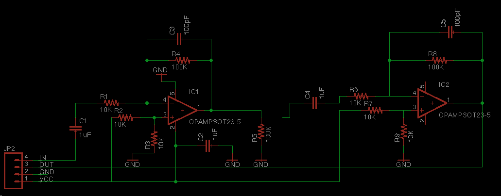
I designed an op-amp circuit to replace the JFET preamp, but I haven't had time to mill/stuff it yet. More details soon...