For
my final project, I am making a ferrofluid screen which displays the
characters you input on the screen. The idea is to have an array of 20
electromagnets embedded in a cast smooth-on plastic and have the
ferrodluid in that.
Making the electromagnets
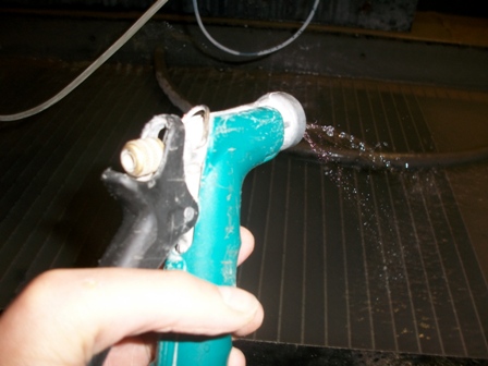
I started by using the waterjet to cut small steel pieces which will be the core of my magnets. To not lose the pieces, we used the plastic mount in the CBA shop and i found out that for this to work you need tabs in the CAD file. Since we had to waterjet above the water, i had to pour water on the part to cool it. The waterjet is impressive above water!!!
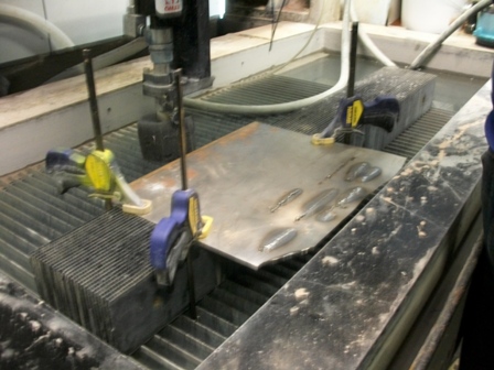
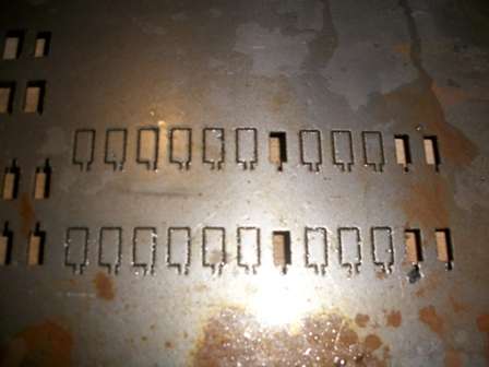
Once that was ready, i used some 30 AWG copper wire to make the coils. Intially, I wanted to make a 300 turn magnet but after testing it on the prototype board, i found that the field from the magnet wasnt strong enough to move the fluid if it was embedded completely. Instead, I noticed that the steel became magnetized, so i opted for a design where i leave a little of the steel out in the fluid to act as the switch. I judged from a couple of trials that 150 turns was enough for that purpose (and less painful to make time-wise).
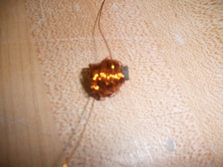
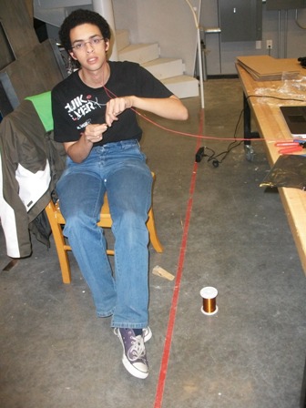
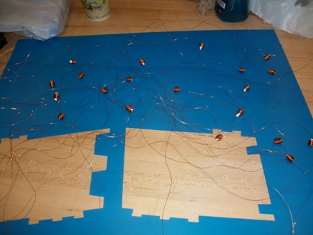
I made 20 of those for the display.
Controlling the electromagnets
To control the electromagnets, I had multiple ways of doing it : One was to use a combination of 4 N mosfets and 5 P mosfets switched by 5 N mosfets to make the 5X4 array and depending on which ones I power, one of the electromagnets would power on. That implied a better control using software which i was hesitant about.
I decided to use 20 pins on the ATMEGA168 to control 20 N mosfets which will power the array of electromagnets. I also needed to add high reverse diodes to protect the components against back current from the inductor after switch-off.
1) Protoype
To check if it is going to work and to understand how to place the high reverse diodes, I made a prototype board using one magnet and tried it. This board has had multiple changes after this schematic.
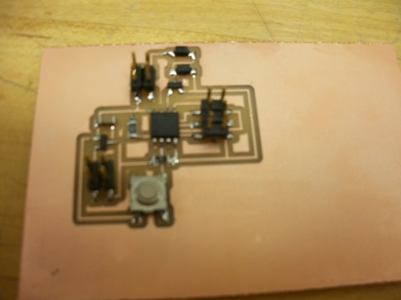
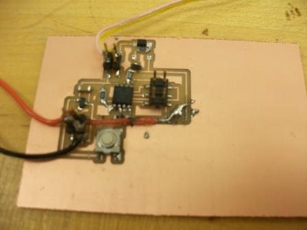
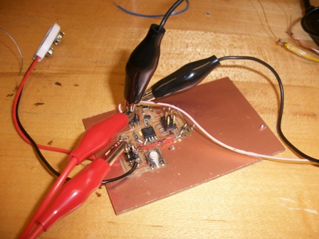
I needed to add a resistance of 1k between the gate & pin (apparently to control the amount of current drawn) and i needed to put the diode in parallel with the electromagnet and not in series for it work. I also learned (much later when it was too late for the final project) that it is a good idea to have a pull down resistor at the gate to avoid problems with the MOSFET at the initial times.
Since alot of surgery had been done to this board, i couldnt use it properly to determine the right PWM to have a good current but not have it overheat.
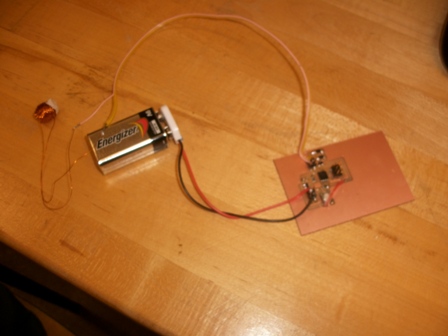
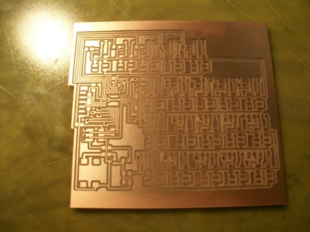
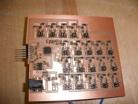
2) Board
As I said, I am using the ATMEGA168 to control 20 N MOSFETS. The power source is a 12V power jack and the voltage is regulated to 5V for use for the microcontroller.
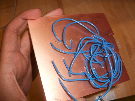
This board was very complicated to wire and I had to resort to using through hole wires to connect everything together. I made the holes using the Drill press & the job took almost 2 hours on the Modela.
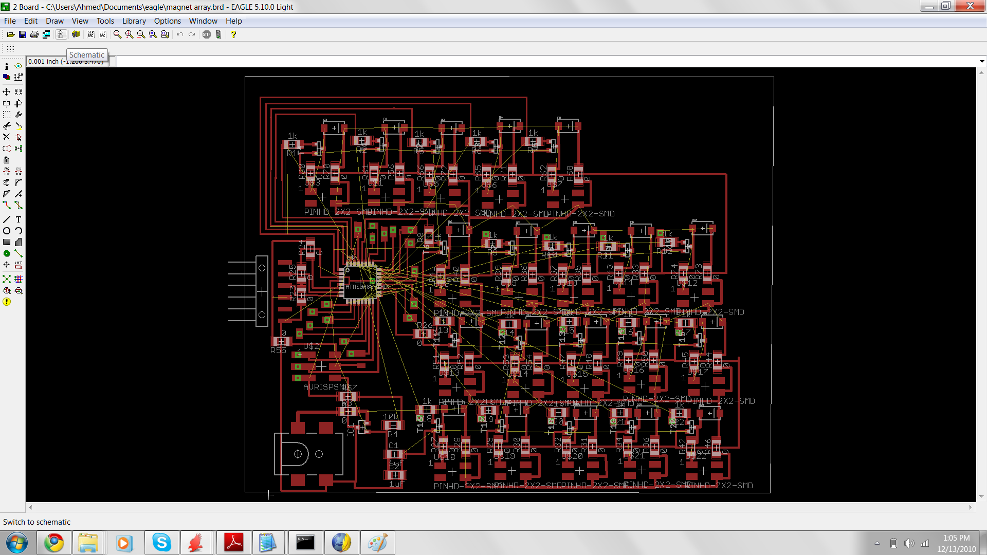
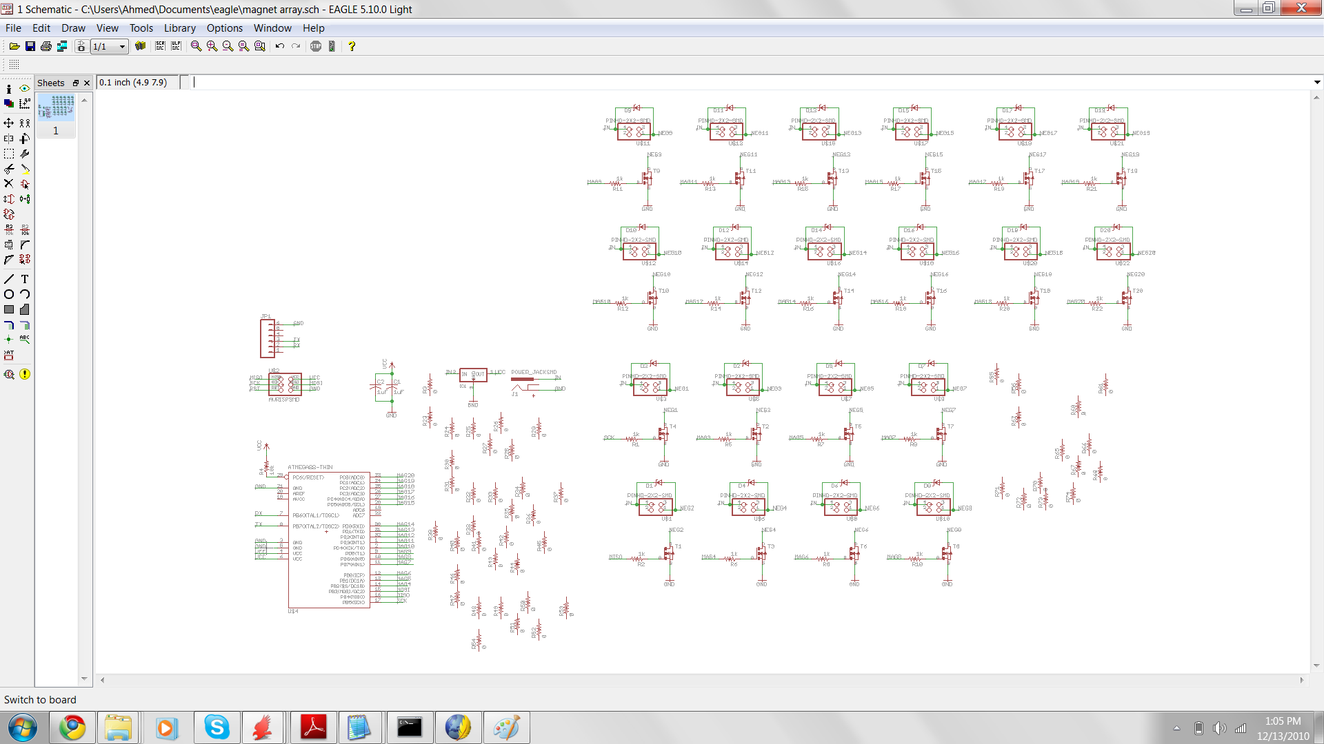
A couple of things I noticed later are that I pulled traces from pins which are not I/O pins so I didnt need to use them. Also, I forgot to connect the 12 V line to the drain lines of the all the MOSFETS. Finally, The 2 pins for ground on the power jack need to be connected (the VCC/inside part is the top most on the schematic, the rest is ground) otherwise the signal is very noisy and does some weird signals.
The board currently doesn't program, I checked on the scope and the power and the regulator seem fine, i check using the multimeter and havent found any shorts so I am stumped as to why it doesnt program since I don't see much else which could go wrong.
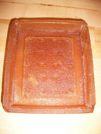
Making the cast of the screen
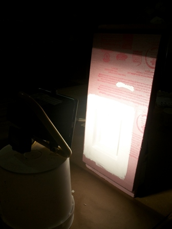
I milled the positive in the pink foam and used 2 layers of Gesso and a layer of mold releaase to coat the mold before making a soft rubber polyurethane (PMC 121/120) negative mold. I used a spotlight to accelerate the curing and that worked out fine. Gesso takes a while to dry though so i recommmend using the spotlight to accelerate the process.
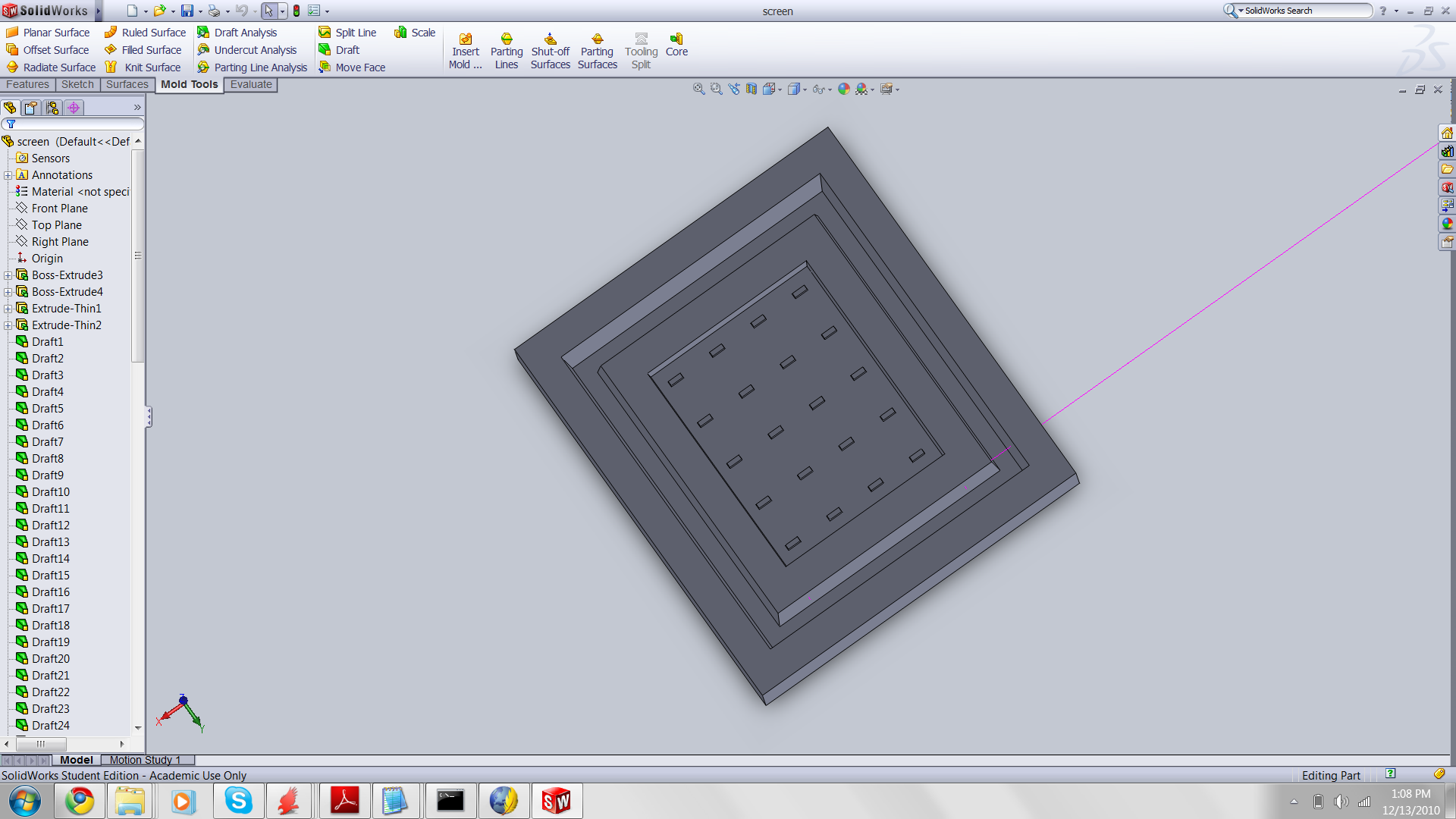
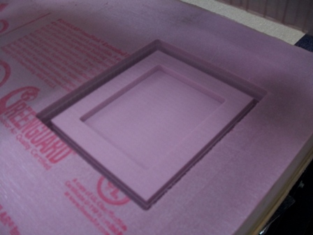
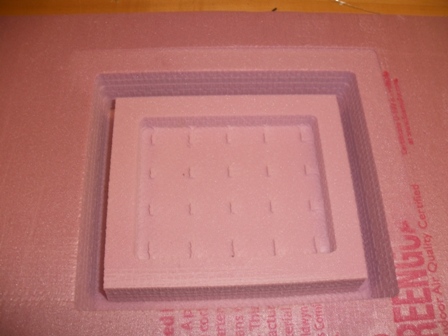
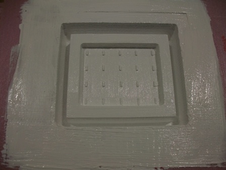
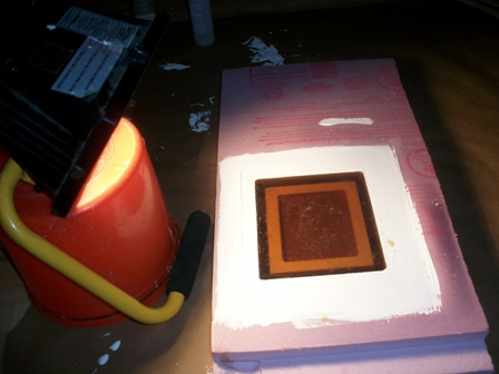
The small squares are for where the tip of the magnet should be protruding.
I am using the smooth cast 326 with the blue color to make the base of the screen with the magnets embedded
Screen Cover
I plan to lasercut a layer of transparent acrylic to seal the screen. That will connect to the base by press fit or using a screw.
Ferrofluid
I have a sample ferrofluid in my lab but i found this home made, easy to make recipe which i intended to use to make my own fluid. This site provides the best home made recipe I found and tje materials are readily available.
Unfortunately, due to the lack of time, I haven't been able to do it so I'll use the sample fluid.
Link to the website for making the fluid : http://www.sci-spot.com/Chemistry/liqimag.htm
Making the electromagnets
I started by using the waterjet to cut small steel pieces which will be the core of my magnets. To not lose the pieces, we used the plastic mount in the CBA shop and i found out that for this to work you need tabs in the CAD file. Since we had to waterjet above the water, i had to pour water on the part to cool it. The waterjet is impressive above water!!!
Once that was ready, i used some 30 AWG copper wire to make the coils. Intially, I wanted to make a 300 turn magnet but after testing it on the prototype board, i found that the field from the magnet wasnt strong enough to move the fluid if it was embedded completely. Instead, I noticed that the steel became magnetized, so i opted for a design where i leave a little of the steel out in the fluid to act as the switch. I judged from a couple of trials that 150 turns was enough for that purpose (and less painful to make time-wise).
I made 20 of those for the display.
Controlling the electromagnets
To control the electromagnets, I had multiple ways of doing it : One was to use a combination of 4 N mosfets and 5 P mosfets switched by 5 N mosfets to make the 5X4 array and depending on which ones I power, one of the electromagnets would power on. That implied a better control using software which i was hesitant about.
I decided to use 20 pins on the ATMEGA168 to control 20 N mosfets which will power the array of electromagnets. I also needed to add high reverse diodes to protect the components against back current from the inductor after switch-off.
1) Protoype
To check if it is going to work and to understand how to place the high reverse diodes, I made a prototype board using one magnet and tried it. This board has had multiple changes after this schematic.
I needed to add a resistance of 1k between the gate & pin (apparently to control the amount of current drawn) and i needed to put the diode in parallel with the electromagnet and not in series for it work. I also learned (much later when it was too late for the final project) that it is a good idea to have a pull down resistor at the gate to avoid problems with the MOSFET at the initial times.
Since alot of surgery had been done to this board, i couldnt use it properly to determine the right PWM to have a good current but not have it overheat.
2) Board
As I said, I am using the ATMEGA168 to control 20 N MOSFETS. The power source is a 12V power jack and the voltage is regulated to 5V for use for the microcontroller.
This board was very complicated to wire and I had to resort to using through hole wires to connect everything together. I made the holes using the Drill press & the job took almost 2 hours on the Modela.
A couple of things I noticed later are that I pulled traces from pins which are not I/O pins so I didnt need to use them. Also, I forgot to connect the 12 V line to the drain lines of the all the MOSFETS. Finally, The 2 pins for ground on the power jack need to be connected (the VCC/inside part is the top most on the schematic, the rest is ground) otherwise the signal is very noisy and does some weird signals.
The board currently doesn't program, I checked on the scope and the power and the regulator seem fine, i check using the multimeter and havent found any shorts so I am stumped as to why it doesnt program since I don't see much else which could go wrong.
Making the cast of the screen
I milled the positive in the pink foam and used 2 layers of Gesso and a layer of mold releaase to coat the mold before making a soft rubber polyurethane (PMC 121/120) negative mold. I used a spotlight to accelerate the curing and that worked out fine. Gesso takes a while to dry though so i recommmend using the spotlight to accelerate the process.
The small squares are for where the tip of the magnet should be protruding.
I am using the smooth cast 326 with the blue color to make the base of the screen with the magnets embedded
Screen Cover
I plan to lasercut a layer of transparent acrylic to seal the screen. That will connect to the base by press fit or using a screw.
Ferrofluid
I have a sample ferrofluid in my lab but i found this home made, easy to make recipe which i intended to use to make my own fluid. This site provides the best home made recipe I found and tje materials are readily available.
Unfortunately, due to the lack of time, I haven't been able to do it so I'll use the sample fluid.
Link to the website for making the fluid : http://www.sci-spot.com/Chemistry/liqimag.htm