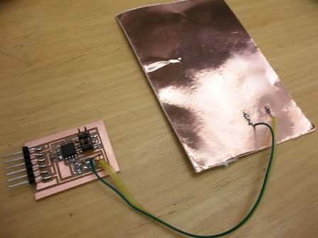
This week, I set out to do 2 sensors : a magnetic field sensor and a proximity sensor based on Neil's step response.
Magnetic field sensor :
This board uses the hall effect sensor described in class.
This took a while to figure out because i had to understand all the vocabulary in the datasheet. And if i have to give a piece of advice, it would be : RTFM!!!. I designed the circuit based on the resolution I wanted using the 1.1 V internal reference then realised that the output of the hal effect sensor was biased so it output 2.5 V when B=0.
The sensitivity of the sensor is 5 mV/G so using Vcc as a ref would have given me really bad resolution for smalle fields. Some quick calculations showed that I wanted the voltage to vary between 2.4 & 2.6 V to get the really high resolution. I decided then to make a voltage divider on one pin and put the sensor on the other and measure the difference. It is bascially the same idea as the wheastone bridge.
I then saw in the datasheet that the noise was about 40 mV and I was trying to measure up to 500 mV so I was worried about the noise. I decided to do a test run of the device by measure +- 0.55 V (ie +- 110 G) by using the voltage divider and the 1.1 V internal reference.
So on the voltage divider side, the voltage is 1.95 V. this means I will measure 0 V difference between the sensor and the divider when B= -110 G, i will measure 0.55 V when B =0 G.
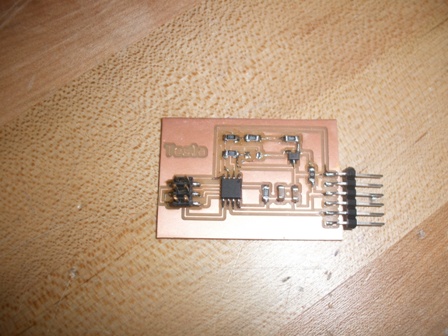
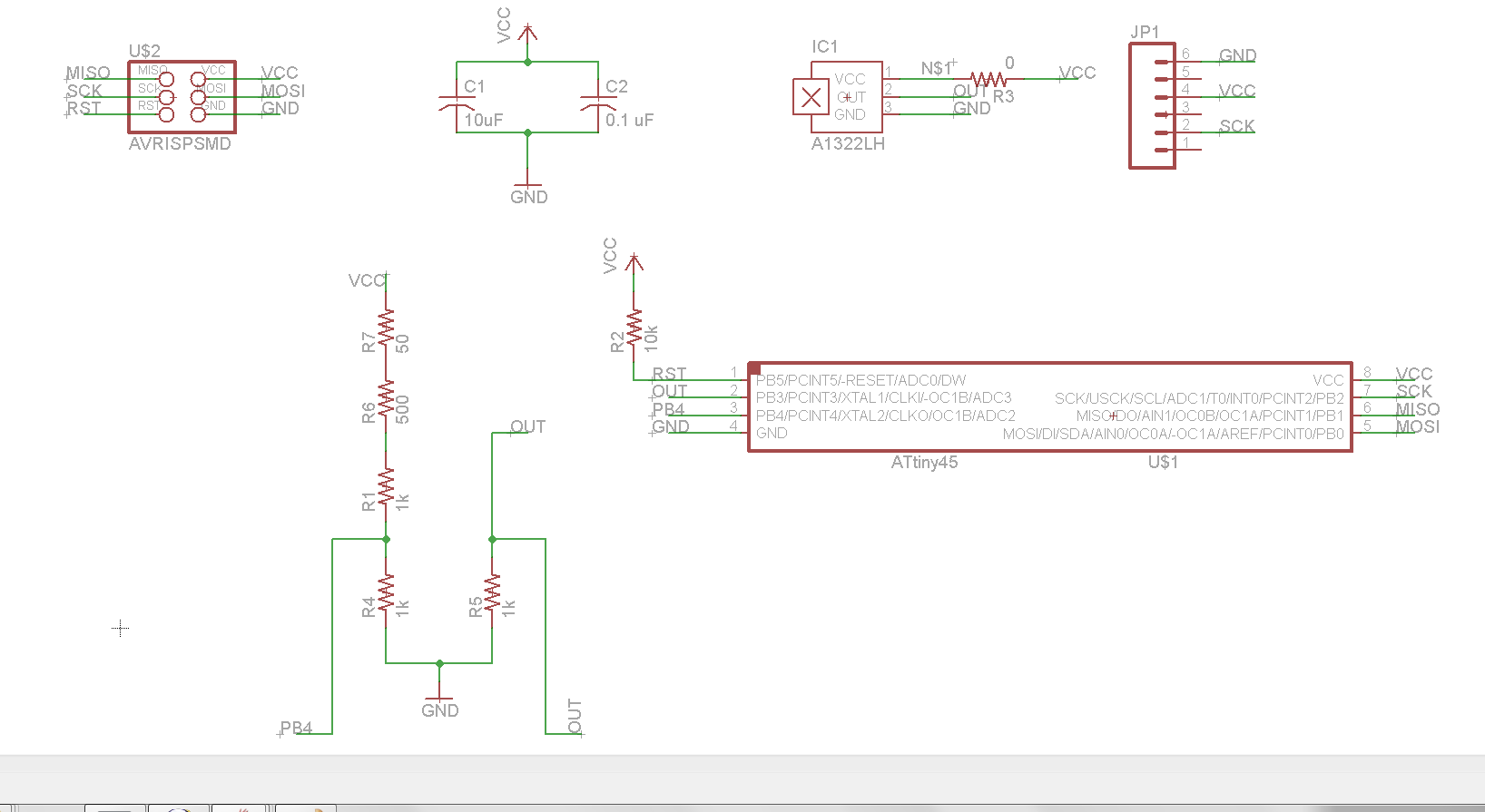
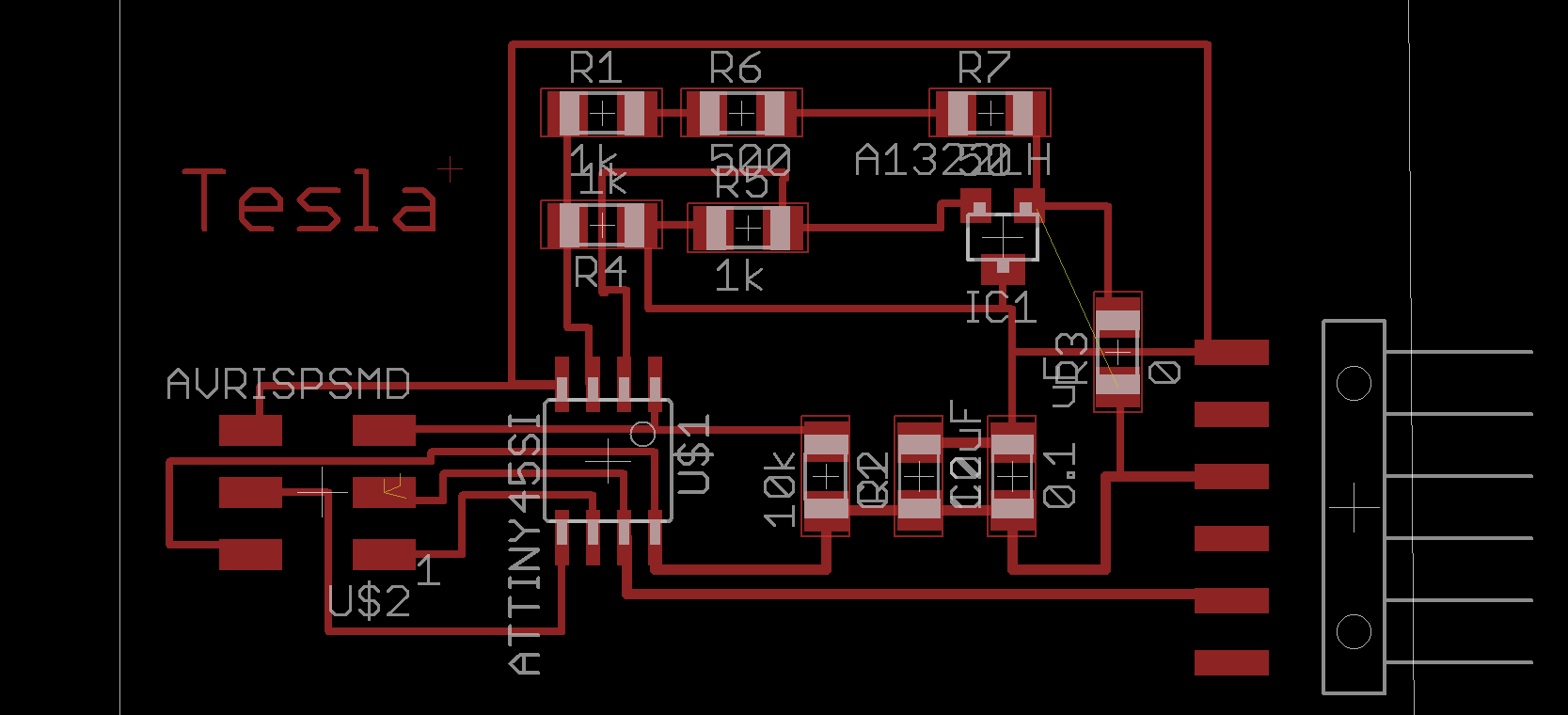
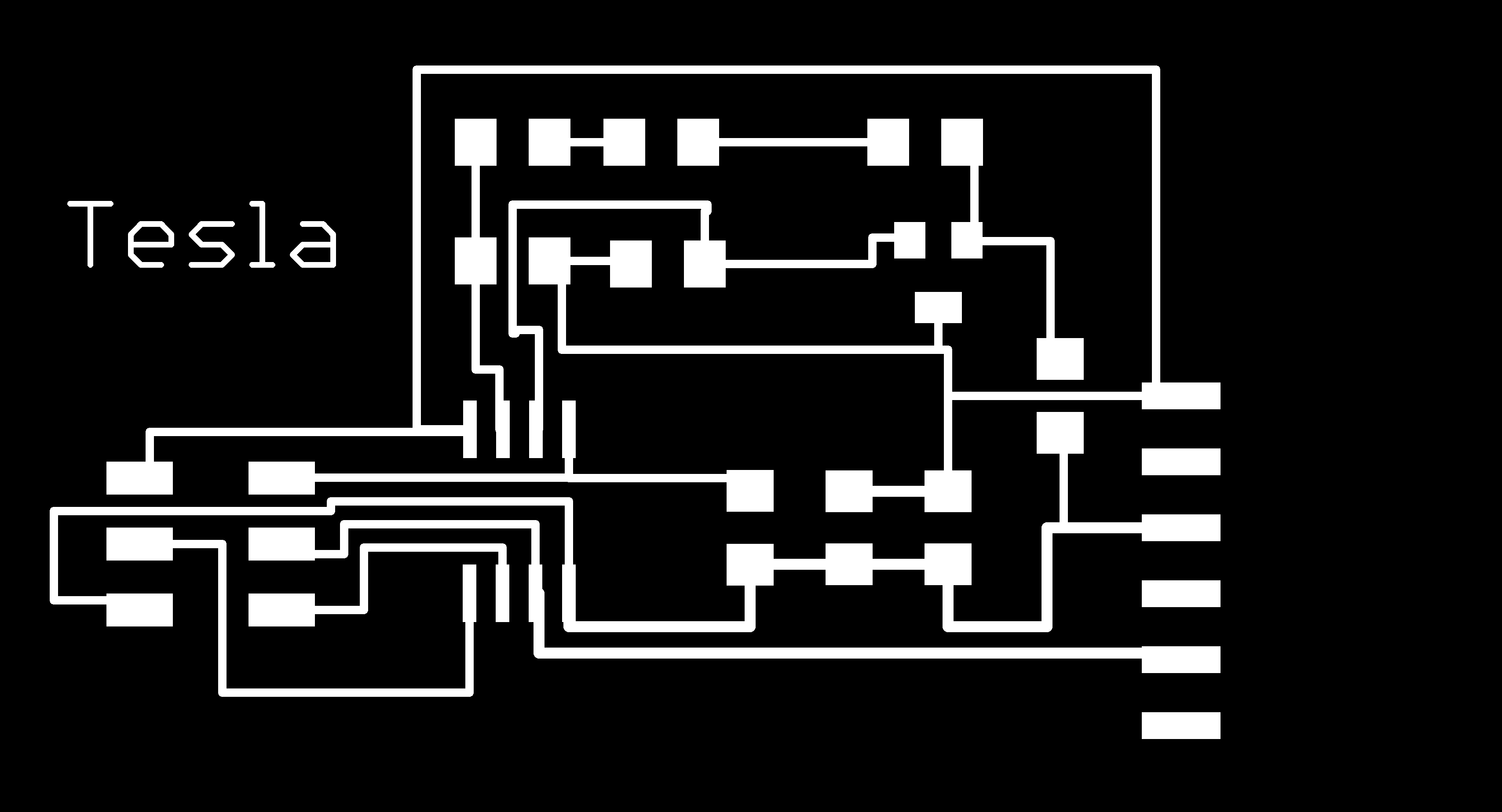
Here is a schematic, the board layout and the png for milling :
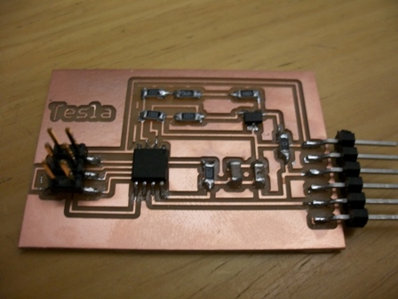
An here is the final board :
I modified Neil's temperature sensor code to work for this and it programmed correctly (according to avrdude) .
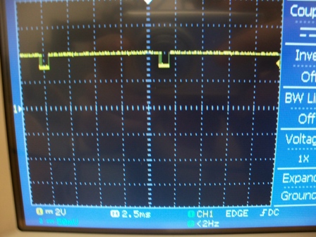
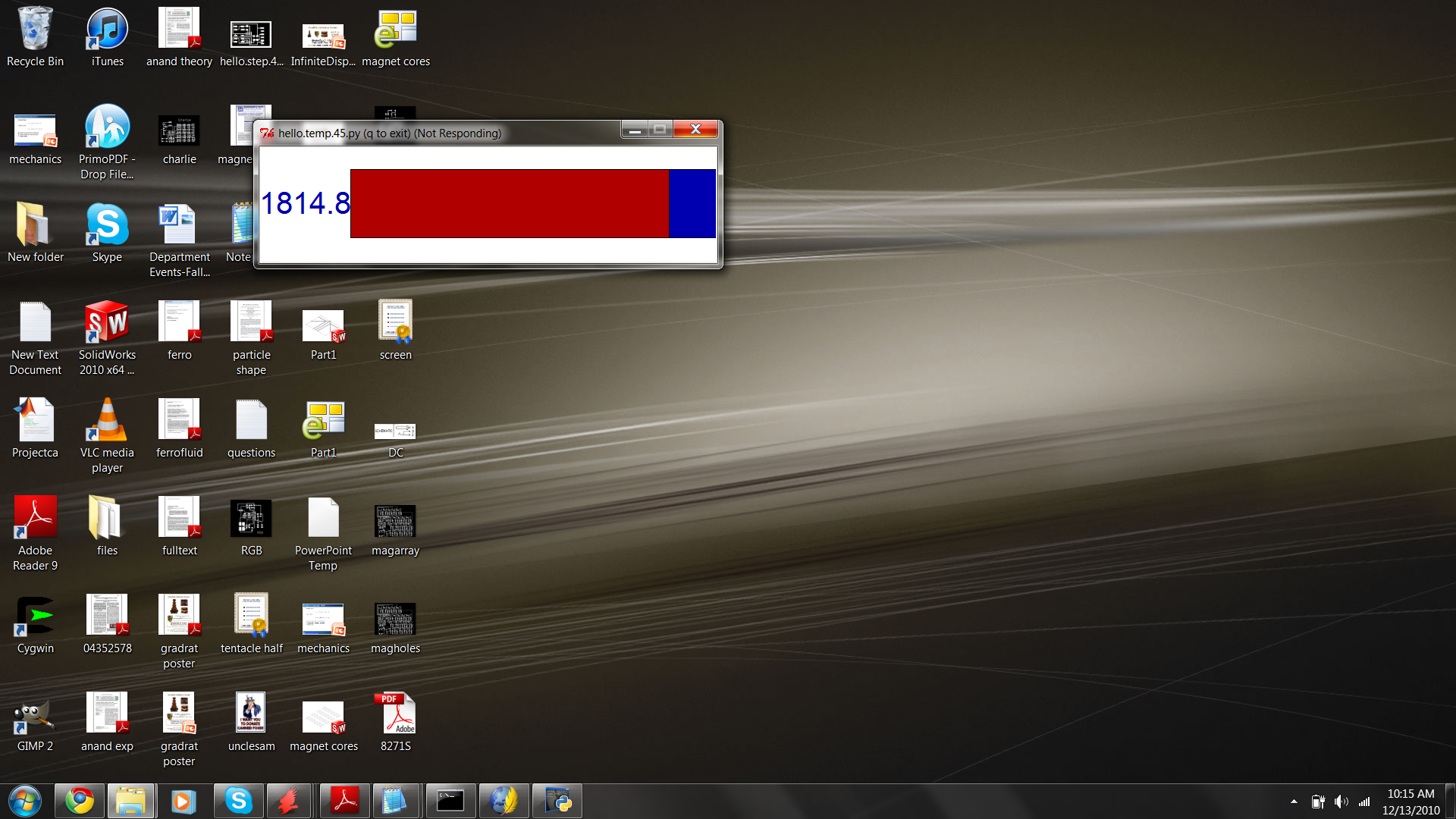
However, whenever I try to run the python side of things, the application freezes and crashes. A bit of testing showed that I cam not actually sending or receiving any bits.
I will try with another computer & cable to see if it is hardware related or software related.