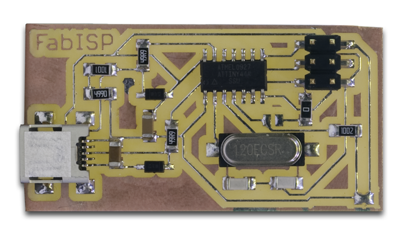
This week, I made the FabISP in-system AVR programmer. This was my first time milling a non-trivial PCB. It turned out pretty well and I can see this process being useful for simple, single-sided boards in small quantities.
In section, I learned how to use the fab modules and the Roland Modela to make PCBs, but the board I used was milled on the Mantis CNC milling machine, which turned out nicer than the one milled on the Modela. My board was milled on a single PCB and then cut apart after milling. I didn't cut the boards apart very well, so the top edge isn't very straight, but it's a functional board.
The video above shows me soldering the entire FabISP over about twelve minutes. I'm used to soldering small (0402 and QFN) surface-mount components, so the FabISP was relatively easy.
While putting the FabISP together, I noted one place where the usual smallest-to-largest, inside-to-outside assembly technique wasn't appropriate. The USB connector would have been a lot easier to solder if I did it before the bypass capacitor that's right behind it.
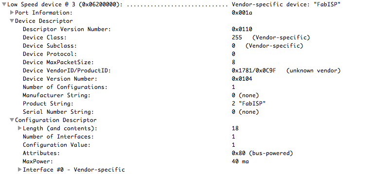
I programmed the board using an AVR JTAGICE mkII programmer. It programmed on the first try and showed up as a USB device:
I haven't tried using it to program anything else yet, since most of the target boards I have around are 3.3V. It would be useful to design a revised FabISP with level shifters so that it could program boards at voltages other than 5V.