This page is a work in progress... ran out of time. Soon the board and source files will be here so you can build your own and program it to play your own songs!
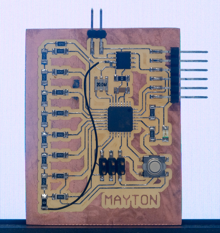
After I finished putting the board together, I quickly verified that I could communicate with the board using a programmer and that the LED and the switch were functional. I don't use AVR Studio for any of my actual coding, but it's great for talking to the chip over debugWIRE and quickly verifying board functionality. Then, I moved on to testing the DAC and buffer, and noticed my first mistake with the circuit.
I had wired up the resistor ladder with the bit order reversed: higher-order bits on the microcontroller were wired to lower-order bits on the ladder. Swapping bit order around in software turns out to be an expensive operation; the options are basically rearranging things one bit at a time (taking many instructions) or using a 256-entry lookup table mapping bytes to their reversed versions. I started with the first approach for testing, and discovered another problem.
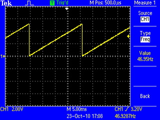
I wrote a simple program that counted from 0 to 255, and output the value on the DAC. That should generate a nice ramp function. However, what I saw was this:
The voltage was increasing, but nowhere near linearly and only with a couple of bits of resolution, certainly not 256 steps. Further testing revealed that only the top few bits had any effect.
When debugging something, one has a tendency to overlook the simple things and focus on the complicated ones. After scratching my head for a while looking at the wrong parts of the circuit, I finally realized that when I picked out the resistors from the shelf, I transposed a decimal point on one of the values and the resistances for one value were ten times higher than they were supposed to be! I swapped out the bad values for what they were supposed to be, and in the process cut a few traces and added some wire to reverse the order of the bits so it wouldn't need to be done in software.
Voilà. That looks more like it's supposed to. Now, with the circuit able to produce analog voltages, I started working on the synthesizer.
Digital audio synthesis starts with a waveform. I used a sine wave, one period of which I precomputed using a Python script and stored in a table in my program. By iterating through the table at different speeds and outputting the values through the DAC, I can produce tones at various frequencies:
Not a bad sine wave. You can certainly see some quantization noise, from only using 8 bits of resolution and a sample rate of only about 12kHz, but it will work.
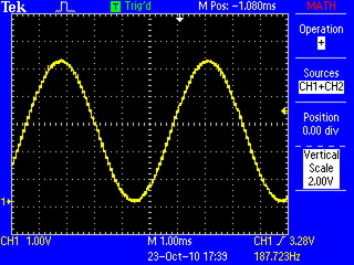
Chords can be formed by having several pointers into the table and moving them along at different speeds corresponding to the different frequencies of the notes in the chord, then summing the values at all of the pointers. Here's a nice C-major chord:
There are no real instruments that instantly start producing sound at some volume level and continue at exactly the same level until the sound stops. Usually, the volume ramps up (sometimes sharply, sometimes more gradually) when a note is played, and falls off when the note is released. In the synthesizer, we get this effect using amplitude envelopes. The amplitude envelopes are lookup tables just like the sine wave. We start with a pointer at the beginning of the table, gradually moving it along as the sound is played and multiply each sample with the value in the table. The amplitude envelope doesn't loop like the sine waveform, and it is played much more slowly (over thousands of samples.) Here's an example of the sine wave with an amplitude envelope applied:
This envelope follows a pretty common pattern: there's an upward slope at the beginning (the "attack") reaching a peak value, then falling off to a mid-level (the "decay") where it stays for a while (the "sustain") before falling off to silence at the end (the "release"). Because of these four segments, such an envelope is sometimes referred to as an "ADSR" envelope, and many different sounds can be achieved by adjusting the slopes and levels of the various parts.
Note that ideally, the waveform would be centered around 0V. Here, the envelope itself shows up as a low-frequency component in the output waveform because I'm using unsigned values with a DC offset rather than signed values, and the DC offset is getting scaled along with the amplitude. In this case, it doesn't really matter since the low-frequency component is well below the audible range. In general, the DC offset is an undesirable thing, since it's pushing wasted power through the speaker, but this isn't exactly a hi-fi setup.
Any function can potentially be used as an amplitude envelope. Here's an exponential decay function:
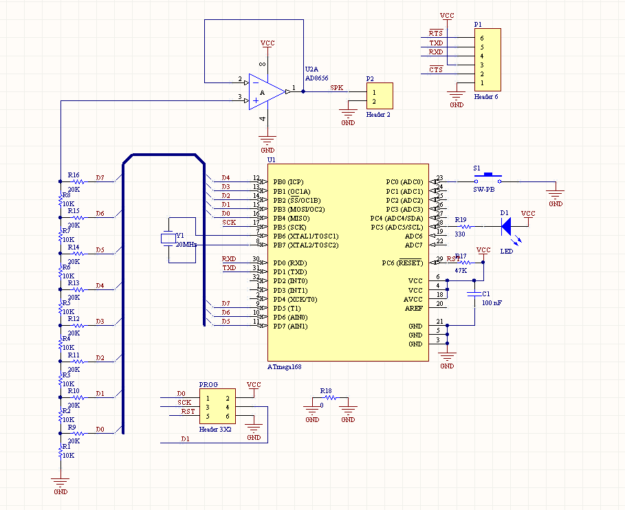
The R-2R ladder DAC outputs analog voltages from 0 to 5V, but with high output impedance; if anything tries to draw much current from the output, the voltage falls off precipitously. Since the speaker takes a fair bit of power, there is an op amp in the circuit buffering the output of the DAC. The op amp is configured for unity gain, meaning that it doesn't change the voltage at all. It simply produces the same voltage on its output as it sees on its input, but with very low output impedance, so it can drive much larger loads.
Normally, in audio circuits, a dual-rail power supply is used, with positive and negative voltages above and below ground in the center, and the audio signal is centered around ground. In this case, half of the time the op amp would be sourcing current, and the other half of the time it would be sinking current. In my simple circuit with a single-ended power supply, the op amp is always sourcing current, which means for the same voltage swing, it has to be able to supply twice the current, since the entire waveform has to "fit" on one side of ground. The op amp I'm using is able to source quite a bit of current (200+ mA) but too high above that and it goes into current limiting, clipping the output waveform. This is what happens when an 0-5V sine wave is fed into the speaker:
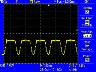
The tops of all of the waves get chopped off, drastically altering the sound. The solution in this case was to add a voltage divider at the input of the op amp, dividing its input (and therefore its output) voltage by 2. This reduces the theoretical output voltage swing of the system, but keeps the op amp from trying to source so much current that it clips the signal.
It's possible to make a decent array of sounds just by applying various amplitude envelopes to sine waves, but a lot more sounds are possible by applying a technique called frequency modulation synthesis. The basic idea is that we take the carrier wave, and slightly modulate its frequency with another signal (in this case, another sine wave.) By choosing the ratio of the modulator's frequency to the carrier frequency (the modulation ratio) and the extent to which we apply the modulation (the modulation index) to control the timbre of the sound.
Here are the parameters for a few of the instrument sounds I am using (defined in
instrument.c):
static const instrument_t instrument_flute = {
    .envelope_index = 0,
    .env_increment = 16,
    .modulation_index = 8,
    .mod_ratio_numerator = 0,
    .mod_ratio_denominator = 1,
    .attenuation = 0
};

static const instrument_t instrument_music_box = {
    .envelope_index = 1,
    .env_increment = 16,
    .modulation_index = 4,
    .mod_ratio_numerator = 36,
    .mod_ratio_denominator = 5,
    .attenuation = 2
};

static const instrument_t instrument_marimba = {
    .envelope_index = 1,
    .env_increment = 16,
    .modulation_index = 4,
    .mod_ratio_numerator = 36,
    .mod_ratio_denominator = 21,
    .attenuation = 2
};
Note that in my code, the modulation_index parameter is actually
used to attenuate the modulator, so lower values result in more
modulation. The ratios are split into the numerator and denominator to make the
fixed-point integer math easier.
To actually play songs with the synthesizer, I needed a sequencer to actually
feed it notes at the right times. A timer interrupt serves as the clock for the
sequencer, keeping time for the song being played. The song data are stored in the
flash program memory. A byte containing a valid MIDI note number is fed into the
synthesizer, and bytes greater than 127 are control opcodes to adjust various
sequencer and synthesizer parameters (see opcode.h for the
opcodes.)
Since this binary format is hard to work with by hand, I created a simple text-based piano roll notation, and wrote a compiler to parse it and turn it into the binary files:
A5	D6	OFF	D4	D5
OFF	OFF		.	.
		A4	OFF	.
		OFF	F5	.
A5	D6		.	.
OFF	OFF	A4	OFF	.
		OFF	D5	.
		F5	OFF	.
A5	D6	OFF	D4	D6
OFF	OFF		.	.
		A4	OFF	.
		OFF	F5	.
A5	D6		.	.
OFF	OFF	A4	OFF	.
		OFF	D5	.
		F5	OFF	.
A5	D6	OFF	A#3	F5
OFF	OFF		.	.
		F4	OFF	.
		OFF	F5	.
A5	D6		.	.
OFF	OFF	F4	OFF	.
		OFF	E5	.
		F5	OFF	.
A5	D6	OFF	A#3	.
OFF	OFF		.	.
		F4	OFF	.
Each vertical column (tab-separated) is a synthesizer channel. Notes are started
with their note names, and ended with OFF. The periods are optional
and just help visually indicate that a note is being played on that channel.
The sequencer clock increments the playhead by one line. I'm using four lines per quarter note, giving me sixteenth-note resolution.
Control sequences that compile into opcodes are indicated in the file by lines starting with an asterisk:
*channels 5
*speed 17
*instrument 0 4
*instrument 1 4
*instrument 2 2
*instrument 3 2
*instrument 4 0
*volume 0 40
*volume 1 40
*volume 2 100
*volume 3 100
*volume 4 110
Click here to hear a recording of the circuit playing a song.
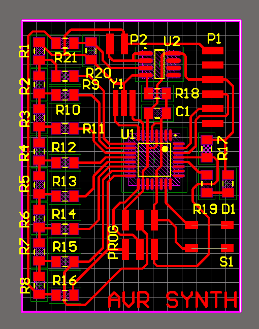
Board files will be posted here as soon as I fix the layout to incorporate the changes I hacked on to make the board work.
Source Code (requires Python to build)