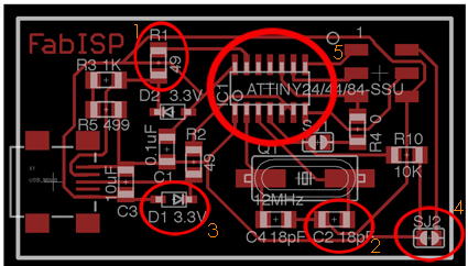
(1) Resistors
(2) Capacitors
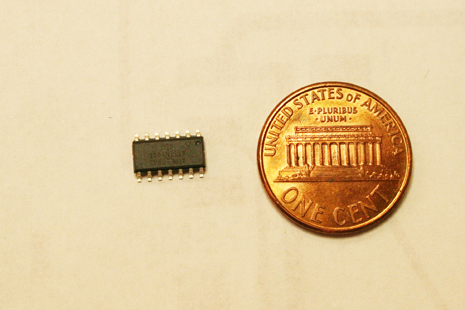
(5) Microcontroller
What is R, C, or J2 or all those thing I am putting in my board
So you don't really know what is it you are putting on your board, even if you have a file that says all those letters. Well here is a little guide on what and why.
These are very simple explanations, to help the ones for those (like me) that do not quiet understand what the light switch at their houses.
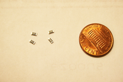
1. R = Resistor
They limit the amount of electricity flowing through your circuit. They vare measured in Ohms and some of the most common you will use on your boards will be 1K ohms or 10K ohms. They don’t have a specific direction to go on your board, so it does not matter if you solder them in one or other direction.
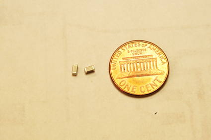
2. C = Capacitor
According to the Computer Desktop Encyclopedia it is “An electronic component that stores an electric charge and releases it when required.” It is measured in farads and, unless noted with a plus sign, it does not have a polarity (you can solder it in any direction). Be careful because the typical surface mounte capacitors you will be using in the class do not have a written indication on it so don’t mix them!
3. D = Diode
They only let current flow in one direction, from anode to cathode (alphabetical order). They are measured in Volts and they do have a specific direction, if you watch the diode closely you will see that it has a line on one of its ends, that marks the cathode side and should go where the line in the eagle board is. LED’s are a kind of diode, so they will have the same symbol on your board.
4. SJ = Solder Jumper
These are just two unconnected traces on your board. You connect them by soldering a junk that joins them and you can disconnect them whenever you want just by taking the solder out.
5. Microcontroller (A)
You will be using different kinds of them, and eventually you will learn a lot about them. It is very very important to note that the symbol has a circular mark that tells you where pin number one goes. If you look carefuly the real microcontroller you will see it has the same dot. Solder the microcontroller so both dots coincide.
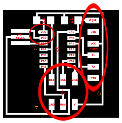
6. Microcontroller(B)
Notice that in this representation there is no dot mark in the microcontroller to indicate pin1. Instead of that one of the pads has a circular end, which means that is number 1
7. AVRISP
This is a 6 pad trace to connect the rainbow cable you will make. Notice it has all rectangular pads, except one, which corresponds to number 1 pin. You should be careful when connecting two boards with the rainbow cable to connect pin 1 in one board to pin1 in the other. Look the colors of the cable ant it will be easier.
8. FTDI
Tipically this is a 6 pin connector for the serial-USB cable. This header comes in lines of more pins so you have to cut it to 6 for using it here.
How to Solder
The theory is that solder will easily flow to the hottest place so the smoothest way to solder components to the board is by heating first the pad to which you want to solder and then touch it with the solder wire. If you have been patient enough the solder will flow easily and you will have a smooth and shiny solder. If it doesn't seem to work it maybe that you are not waiting enough in the heating process.
The steps to stuff a component on your board are:
First: Heat one of the two pads that correspond to the component you are soldering and apply the solder wire to it so the pad is left with a little bit of smooth and shiny solder on it.
Second: Using the tweezers (unless the component is big enough, which unfortunately is almost never the case) hold the component on the pads and reheat the copper until the solder melts and flows on to the component.
Third: Using the same technique of heating the coppper board solder the other end of the component.
How to de-solder
After all my advice you still managed to put the microcontroller upside down...It´s ok, this has a very easy solution.
Using the tweezers hold the component you want to desolder from your board and with your other hand blow hot air to your board over the place of the incorrect component. At some point the solder will melt, the board will fall and you will have on the tip of the tweezers the component you took off.
NOTE: The video is an example of how to do it, but it may be better to, first, leave the board on the table and blow hot air on it and, after a while, lift the board up with the tweezers picking up the component you want to take out. In that way you prevent some problems that sometimes happen when the component you are taking off moves or takes out someting else in the process.
How to take some solder out
Ok now you put the microcontroller in the right way, but since those pins are so close you messed up and they connected by a big piece of solder.
You can undo this using the copper braid. Just hold it to the solder you want to take out and, using the solder iron, heat the braid. At some point the solder will transfer to the hotest place which by now is the braid. You may want to hold the braid with tweezers since it will be the hottest place in the board.