week 7: Input devices


For this week we had to choose a sensor, create a board and program it to have a graphical output of the sensed information to the computer. I wanted to test different sensors, so I decided to make three boards using the phototransistor for light sensing, the microphone for sound and one created by me to sense water through its resisting value.


LIGHT SENSOR


I redesigned the light sensor board in Eagle and added an LED that turns on when there is no external light and turns off when the sensor detects sufficient light, so besides seeing the changes on the screen you can see, in the board, how the sensor works. I modified a little Neil's original C program in order for this to happen.


SOUND SENSOR


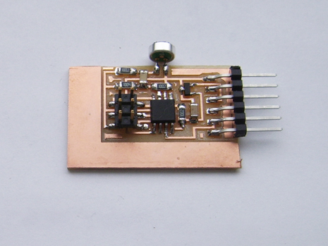
After the light, I tried the sound sensor. First I attempted to redesign the board in Eagle, but I couldn't, so I decided to use Neil's original design. I milled it, stuffed it, plugged it and tried to program it, but nothing happened, except that smell... where is it coming from? .... my board!!! It had gotten really hot, so I unplugged it and tried to figure out what I had done wrong. The microphone was connected in the wrong direction, so I took it out and soldered it again, but still the board gets super hot. I tried to check everything and I could not find the problem (and yes, I checked, and the microcontroller is connected in the right direction), so I decided to leave that project for later.
 

WATER SENSOR


Then I wanted to try something for my final project, so I decided to try a Water sensor. Basing on some information I found on the internet I created my own sensor: two copper plates shaped as combs that don't make contact unless something, like water, touches both.
I tested the sensor with a multimeter and it worked. With one drop of water connecting the traces the resistance started at 150K, and went up. With 3 drops of water it started at 30K and went up slower, and with a lot of water on it it would start at around 10K and went up really slow.
For the board design I used the same I had for the light sensor and connected the water sensor with two cables to where the phototransistor was. For the program I also used the same code I had for the light, but this didn't go as well as planned, because the measurements go crazy. The bar is always jumping to high values which makes really hard to see the real water resisting value. Between the jumps you can still see the values go down as more water is added, but I have to check what is wrong.


Other values with no correlation to the amount of water.