My Goals
This week's assignment was to create a circuit that had some type of interesting output device, and I decided that I would focus on using a speaker for my board. This meant I had to learn about Pulse Width Modulation (PWM) and it offered a few unexpected challenges.
I had two goals for the week. The first was to create a simple sound device just to get the basic concept working -- I decided to create an annoy-o-tron, which is a board that you hide in someone's office and it beeps once every few minutes, but not often enough to be easily found.
The second task was much more complicated and it was partially for my final project: I wanted to create a series of "nodes" that each represented a unique note. EAch node could then be chained together and plugged into a receiver with a speaker. The receiver would be able to read how many nodes were chained and in what order, and would play nodes' notes in the order they appeared.
Task 1: Annoy-o-tron
Since the annoy-o-tron idea really only needed a board with a speaker, I decided to build the "receiver" from the second task at the same time.
The milling and board design was straightforward -- no fires this time -- but when I ran my first test of the speaker I noticed a few pieces of interestingness:
- The speaker was quiet.
- The speaker was hot.
At this point I sent out an email to the group to see what could be done. One thing worth noting was that I was powering the speaker with 5v instead of 9v, which might be an explanation for the silence (and possibly even the heat?). I wasn't able to detect too much of note on the oscilloscope but then again I had a conflict during the oscilloscope training so I was probably doing something wrong (will be trying again this afternoon with a trained expert).
Verdict: Partial success! It annoyed me, anyway.
Task 2: Chained nodes of doom
So here is what I want in the long run:
- An unspecified number of total nodes.
- An unspecified number of chained nodes.
- An arbitrary order of nodes.
- The ability to have gaps between nodes (i.e. slots that don't have nodes in them).
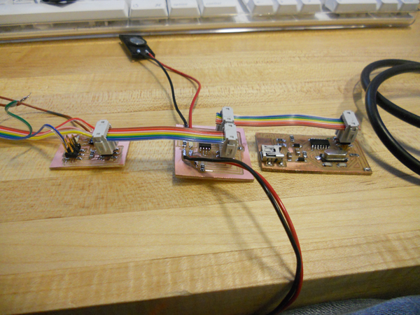
My solution involved three types of board: A receiver board, a slot board, and a node board. The slot boards would be chained together to create the spaces, the node boards would contain the actuall node information and calculate their index, and the receiver board would tell the nodes when to talk.
Here is a diagram of the concept:
To explain what is being communicated:
- GND - the ground line.
- VCC - the voltage line.
- RX - the line that the receiver can use to send messages to nodes.
- TX - the line that the nodes can use to send messages to the reicever.
- BASE - a constant voltage that indicates the voltage of the first position.
- POS - a voltage that decreases across each space using voltage dividers.
The idea was that with these pieces of information, I could have each node calcualte it's position by dividing POS / BASE, and then I could have the receiver ask each node for it's value.
For this week I merged nodes and spaces into a single board, since it added more complexity with no immediate benefit for this particular project.
I milled and stuffed three of the nodes, but I made a silly, although intentional, design mistake. The 6-pin connections were NOT linked into the programming pins. I did this beacuse I was using all of them and knew that I couldn't reliably use the reset pin, but I *should* have routed all of them except that one pin. Instead, I had to solder 6 wires onto my node processors' pins in order to program them.
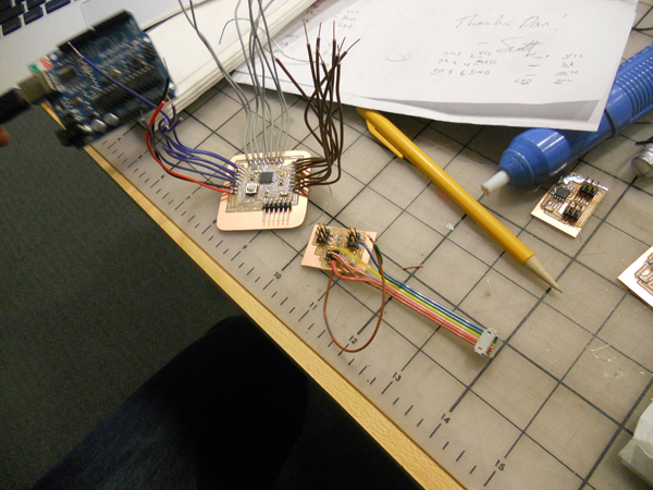
My board is the lower right one there (the top is Phil's fabduino, which puts my mess of wires to shame)
I finally managed to program my node! Everything was poised to work properly! I had the reciever sending out signals over the appropriate pin, I had the node programmed to listen for signals and respond with it's note, and I had the code to play the speaker all written up
I plugged it in, anxious for success. And then... silence.
I spent quite some time trying to figure out what was going on. It looked as though the node wasn't able to properly index itself. I unfortunately wasn't able to finish the debugging session because I was about to miss the final train -- plus my speaker had sadly melted.
Verdict: Partial failure. Lots of progress and lessons learned on the node chip design, but my three note alternating interface needs some more time to pan out.