Stepper Motor control
Milling and Stuffing the board:On the Modela with the fab modules, I milled a board that has holes for wires to connect to the stepper motors and the parallel header and pads for the MOSFETs to switch the signals from the parallel cable. It took a bit longer than I had hoped: maybe I'll use fewer contours next time. I extracted a parallel header from a trashed motherboard and soldered it to the board. Unfortunately, all of the parallel cables that I could find were male-female, and I needed male-male. So, I took a trashed one apart and replaced the female connector with a male one.
EMC2 control:
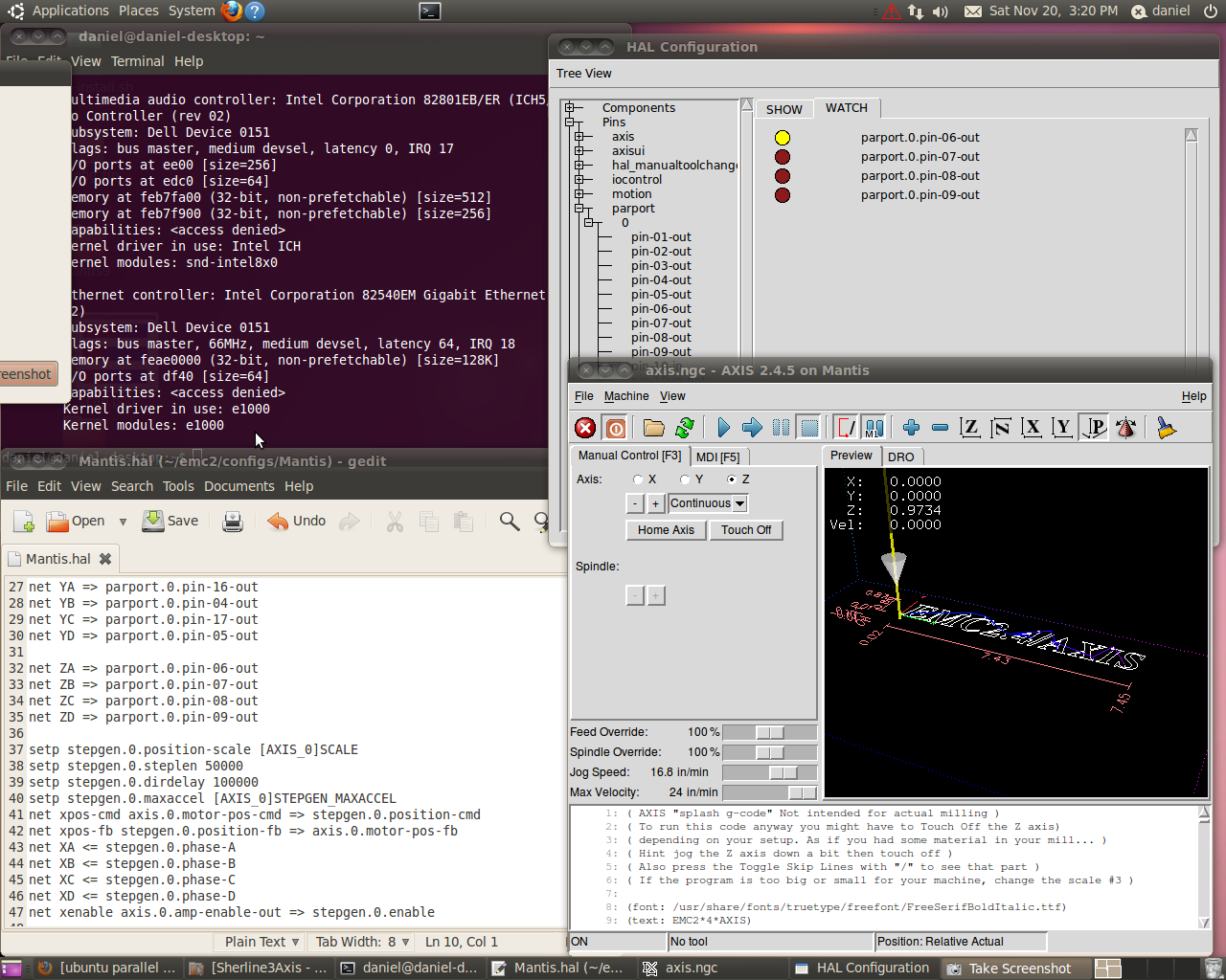
The EMC2 software controls the stepper motors over a parallel connection. The signals from the computer control MOSFETs which dump power to the stepper coils. I used a 7.5V wall wart to supply external power for the 7V rated stepper. I used the EMC configuration from David Carr's site, but had to modify the port address. I had some problems connecting the correct board leads to the correct stepper wires, but eventually figured things out using (among other things) the Watch functionality in the HAL status panel of the EMC software.
Correct connection of stepper leads to the board:
This stepper is unipolar. For my final project, I'll be using bipolar motors which will require three (3-axes) driver boards and chips in addition to the parallel board
