Microcontroller Inputs
Board:I milled my step response board on the CBA shop modela without any problems. I think I'd like to use the Mantis for the output week board as I've been using the reliable Modela exclusively so far. I stuffed the board in the Arch shop without any trouble either. There were no 1x6 pin headers around for the FTDI cable, so I cut a 2x3 in half and used that. I also attached a 2x2 header to the board to make it easy to remove the capacitor plate wires. The header connector was a bit too thick to fit next to the ISP connector, so I shaved down the plastic a bit. For capacitor plates, I cut out two small squares of metal coated tape.
Programming:
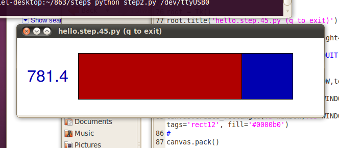
I finally got around to setting up an ubuntu computer (I'll be using it to control my final project 3-axis machine) in my room, so programming the board was much easier because I didn't have to use all the work-arounds the Windows requires. I was able to flash my step.c program to the board within 10 minutes as compared to the hours it took me two weeks ago with Windows. The next task was to get output from the microcontroller to display on my computer through the FTDI serial connection. It took a while, but I eventually figured out how to run a simple Python program with arguments for the serial/USB port. I then modified the code provided by Neil to produce my own step2.py that displayed a number corresponding to the capacitance in the plates. I had some unresolved troubles with the framing (my code would hang in that while loop indefinitely). I looked through the Tkinter documentation online and I am now comfortable working with it. I haven't touched Python in a while and it was really helpful to go through the code line-by-line to get my bearings back.
