3

:: dogiChow ::

08 // Input devices - EEG

The task was to sense something from the world with an MCU and than display that somehow on our computer. So this week we dive from the Physical to the Digital (Virtual actually, but Digital sounds better). This week my project idea was to use my brain waves as an input device. EEG is the method of reading your brain activity by measuring very small voltage changes on the skin of your skull. The voltages to be measured are very small, on the scale of 10-100 uV and with a base frequency around 30Hz, which is alarmingly close to the surrounding 60 Hz. In order to measure them a LOT of filtering, noise canceling and amplification is needed. As a base of my circuit I used the EEG project that was started at CalArts some years ago. The project can be found here: __ Adam Overton __ .

Circuit design

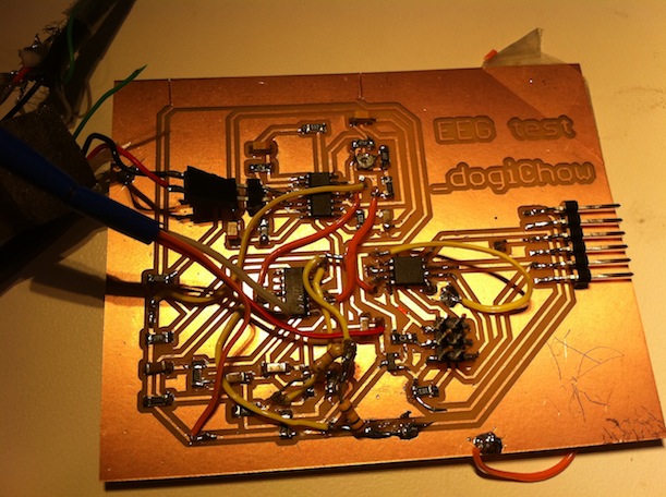
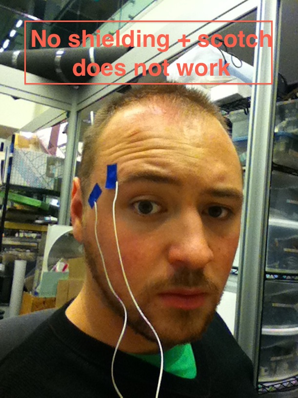
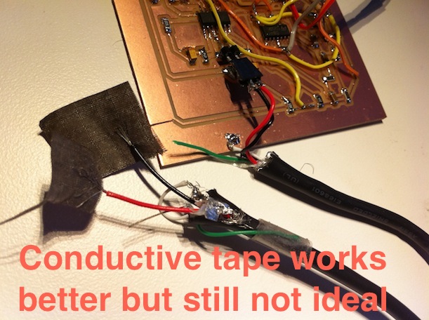
The original circuit that takes up 90% of my design was made by the gentleman that I mentioned above already (Adam Overton). I extended it with a microcontroller and some additional signal conditioning to get rid of some noise (that did not work out that well after all). Here is my circuit:

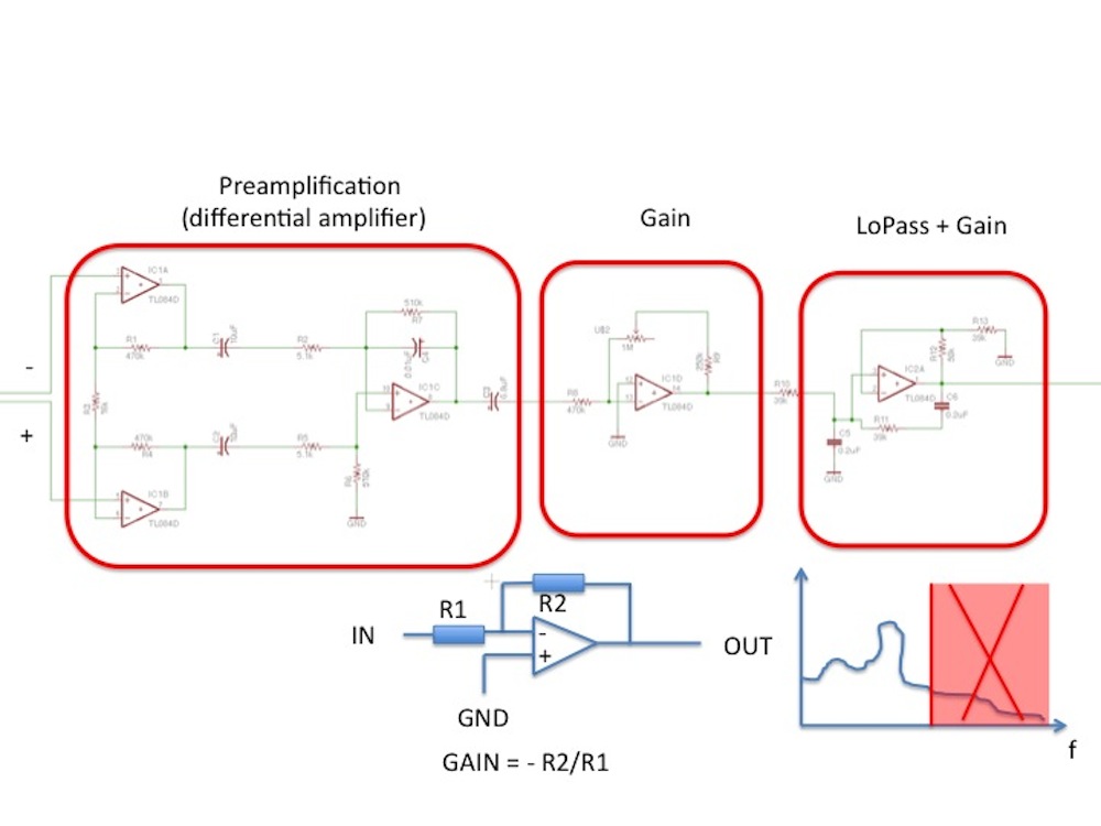
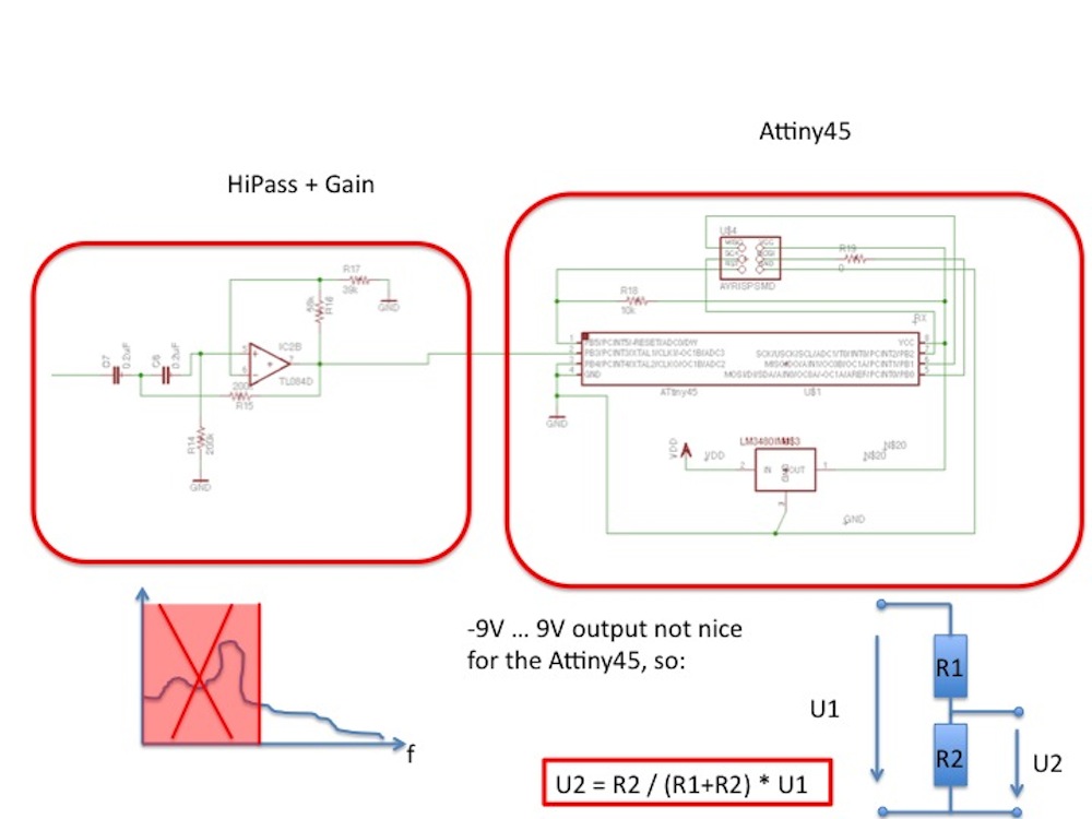
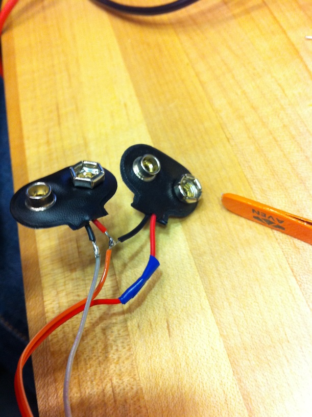
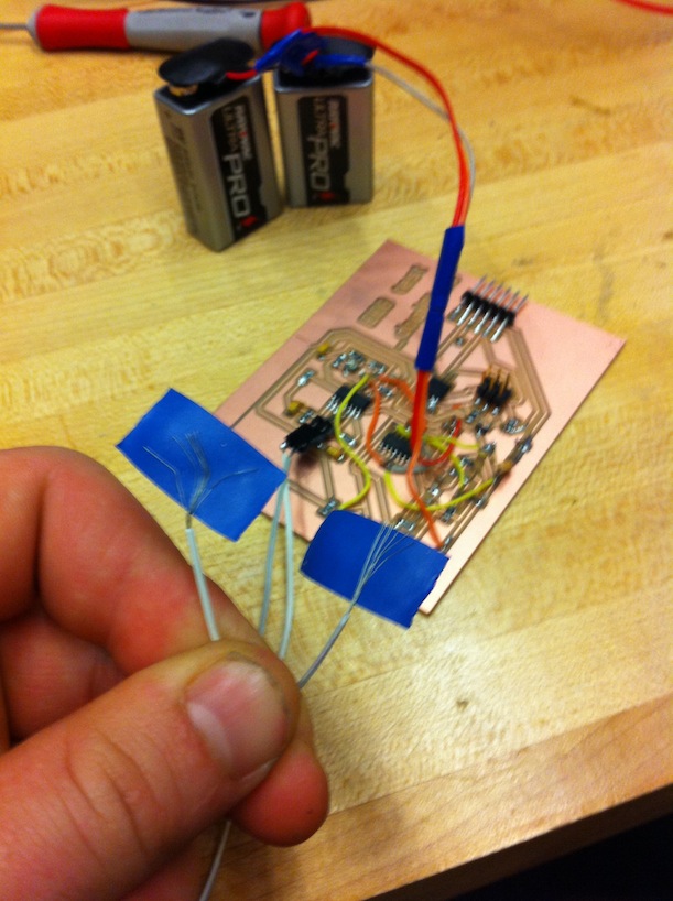
In the circuit I have two 9V batteries, the reason for this arrangement is the differential amplifier that needs symmetrical power. Routing was very hard, I couldn't do it without a bunch of wires criss crossing. Here is my final board:

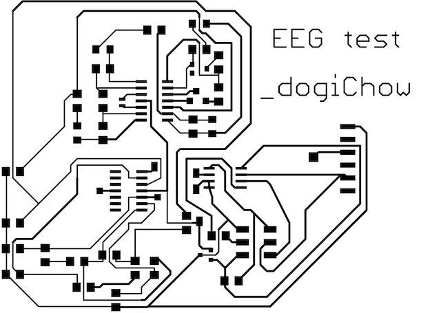
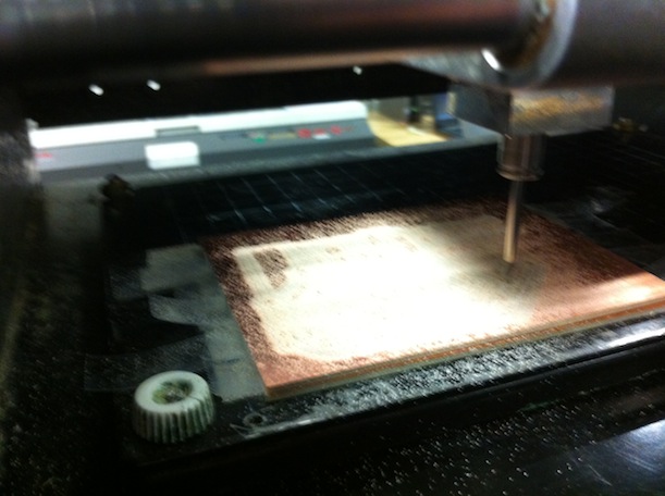
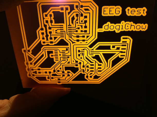
Then I went on and milled my board. It was a fairly complicated board and with a setting of 4 for the speed it took around an hour to mill it (Sorry Matt and Masoud :( ) ... Than I stuffed my board with some nice electronics

After I tested and destroyed an Attiny by connecting the wrong wire to the ADC I finally got the right signal and my little AVR was tweeting me what's going on in the world. Next step were the electrodes, I tried some of them, namely: scotch tape (doesn't work), conductive tape, some gel that I got at MIT Medical. Well, non of them really work. You need good electrodes, like THESE. Also the 50/60Hz noise is going to kill your application you need good electronic shielding .. I used an old USB cable that has a coating around the wires inside (Physics: Faraday Cage) .. you solder the coating to the ground and your good to go.

If you want to go professional take a look at this:

Electrodes positioning:
Small metal discs called electrodes are placed on the scalp in special positions. These positions are identified by the recordist who measures the head using the International 10/20 System. This relies on taking measurements between certain fixed points on the head. The electrodes are then placed at points that are 10% and 20% of these distances. Each electrode site is labelled with a letter and a number. The letter refers to the area of brain underlying the electrode e.g. F - Frontal lobe and T - Temporal lobe. Even numbers denote the right side of the head and odd numbers the left side of the head.


More here
ViZualiZation

Now I have some data (that is unfortunately absolutely not correlated to anything that I do). I built this vizualization around it. Hope you will like it. Source code in openFrameworks below, along with Eagle files and everything!


FILES
www.flickr.com
Dögi's How to make almost anything? photoset Dögi's How to make almost anything? photoset