Two-way XBee radio communication
There are two simple modes for using XBees:
- direct input/output communication - the pins of one XBee are directly linked to the pins of the other XBee. No external microcontroller is required, but there is also no opportunity for programming logic
- "wires" for serial communication - the XBees behave like wires between the transmit (tx) and receive (rx) pins of two separate microcontrollers.
Basic supplies to get started:
- 2 XBee series 1 radios (I used the regular version, not pro)
- 1 XBee Explorer USB board
- 1 USB-mini cable
- a terminal program - I used Tom Igoe's Xbee radio terminal program which runs in Processing.
I. Choose addresses
Each XBee needs four ID numbers: channel (CH), Personal Area Network ID (ID), source ID (MY) and destination ID (DL). To figure out addresses for your two XBees, fill out the following with numbers in the specified range:|
XBee A: CH: 10 - 19 (or 0x0B to 0x1A in hex) ID: 0 - 9999 (or up to 0xFFFF in hex) DL: 0 - 9999 (or up to 0xFFFF in hex) MY: 0 - 9999 (or up to 0xFFFF in hex) |
XBee B: CH: same as CH for XBee A ID: same as ID for XBee A DL: must match MY of XBee A MY: must match DH of XBee A |
|
XBee A: CH: 15 ID: 1211 DL: 5656 MY: 3434 |
XBee B: CH: 15 ID: 1211 DL: 3434 MY: 5656 |
II. Configuring the Xbee for serial communication
1. Press the first XBee into the XBee Explorer board, connect it to your computer using the mini-USB cable, and run the XBee radio terminal program.2. To see if the XBee is speaking to the terminal, type "+++" and wait. This command calls the attention of the XBee. You should see "OK" appear
3. Next, configure your XBees by typing in the AT commands. For example to set the CH to 15, type "ATCH=15" then hit return. You should see "OK" appear, which signifies that CH has been set. If not, you may have waited too long before hitting "+++" and sending the next command. If this has happened, imply type "+++" again, wait for the "OK," and quickly enter in your AT command. When you've configured all of the ID numbers, type "ATWR" and then hit return to save it to the XBee.
For example, to configure XBee A using the IDs above, you would connect XBee A, run the XBee terminal program and type in the following:
+++
ATCH=15 (RETURN)
ATID=1211 (RETURN)
ATDL=5656(RETURN)
ATMY=3434 (RETURN)
ATWR (RETURN)
Then to configure XBee B using the IDs above, you would connect XBee B, run the XBee terminal program and type in the following:
+++
ATCH=15 (RETURN)
ATID=1211 (RETURN)
ATDL=3434(RETURN)
ATMY=5656 (RETURN)
ATWR (RETURN)
To check that you've configured the XBee ID properly, type the command without a value. For instance to check that CH has been set to 15, you would type in "ATCH" and "15" should appear.
4. After configuring both XBees, they are now ready to be used as "wires" in serial communication. Simply connect the XBees to the microcontrollers by connecting tx to rx (the transmit tx of the microcontroller goes to the receive pin rx of the XBee, and vice versa).
III. Setting up direct input/output communication
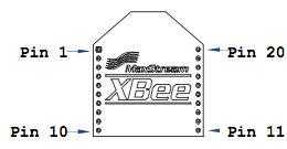
The XBee has 9 input/output pins, 6 of which can read analog values:(A = analog input; D = digital; I = input; O = output)
|
Function
A0/DIO 0 A1/DIO 1 A2/DIO 2 A3/DIO 3 A4/DIO 4 A5/DIO 5 DIO 6 DIO 7 DI 8 |
Pin # 20 19 18 17 11 15 16 12 9 |
AT Command D0 D1 D2 D3 D4 D5 D6 D7 D8 |
|
ATDn = 2 for analog input
ATDn = 3 for digital input
ATDn = 4 for digital output, LOW
ATDn = 5 for digital output, HIGH
ATDn = 0 for disable
To make an input/output pair, simply enable a pin on one XBee as input and enable the matching (same number) pin on the other XBee as output. For example, to use pin 18 (D2) as digital input on XBee A and digital output HIGH on the XBee, configure using "ATD2=3" for digital input and "ATD2=5" for digital output. If you decide that you don't need such a function, set "ATD2=0" for both XBees. Don't forget to enter "ATWR" to save your configuration! Following the example, in the terminal program,
For XBee A, you would type:+++
ATD2=3 (RETURN)
ATWR (RETURN)
For XBee B you would type:
+++
ATD2=5 (RETURN)
ATWR (RETURN)
Note that digital output pins can be set to output only LOW or only HIGH. Once this is set, when XBee A sense a HIGH input, XBee B will output HIGH.
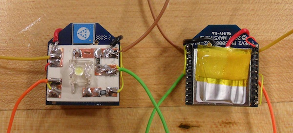
After configuring the XBees, you simply need to complete your circuit, and power the XBees. In my messenger cranes project (see week 12), I used the direct input/output configuration and a 3.7V li-ion battery.
Back to index